
Installation guide

Kaleidescape Part No. 101-0105-00 Rev 3 Page 39
Kaleidescape Installation Guide Physical Installation
Wireless and powerline connections work well for providing Internet access
to the Kaleidescape server, for connecting control systems, and for
accessing the browser interface from a computer. However, a wired
Ethernet network is required between the Kaleidescape components
because of the small tolerance for latency while streaming movies or music.
Wireless LANs
A wireless router (or router and Wireless Access Point (WAP)) can be
connected to a DSL or cable modem to provide wireless Internet
connectivity. To connect a Kaleidescape server to the Internet, connect a
wireless bridge (sometimes called a “wireless game adapter”) to the
network connection on the Kaleidescape server. Follow the instructions for
the wireless bridge to establish a connection.
Using channels that are five channel numbers apart decreases the channel
cross-talk and improves performance. In the United States, only channels 1
through 11 are available, which means that the only three wireless networks
that do not overlap are channels 1, 6, and 11.
Powerline Communications
Powerline communication (PLC) uses electrical wiring to interconnect
segments of an Ethernet network. There are several proprietary PLC
standards, including HomePlug, HD-PLC, and UPA. All equipment used in a
setup must have the same standards.
To connect the Kaleidescape server to the Internet using a powerline
network, plug a powerline adapter into an electrical outlet, and then to a
router or switch with Internet access. Install a second powerline adapter
near the Kaleidescape server, connect the adapter to the network
connection on the Kaleidescape server and an electrical outlet.
Note: Because standards vary, Kaleidescape recommends using two powerline
adapters of the same make and model.
Configuration Examples
Any Kaleidescape server can be connected to the Internet with wireless or
powerline networking equipment. Depending on installation requirements,
many configurations are possible if the connection between player and
server always uses Ethernet cabling.
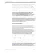
Figure 3-10 is a sample configuration for the Mini System. A wireless access
point (WAP) or powerline adapter is connected to a router. The router is
connected to the Internet access device (such as a cable or DSL modem). A