
Installation guide

Kaleidescape Part No. 101-0105-00 Rev 3 Page 38
Kaleidescape Installation Guide Physical Installation
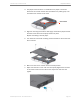
3. Connect appropriate A/V cables. Refer to Table 3-2 for cable restrictions.
4. Connect control cables. The Music Player can connect to two types of
controllers.
0 Serial controller
0 Ethernet IP
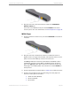
To connect serial controller cable. see M500 Player IR cabling
instructions above. No additional cabling is required for Ethernet
(TCP/IP) controllers if the controller is part of the network.
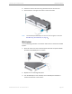
Mini System
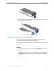
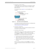
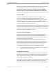
1. Connect an Ethernet cable from the port labeled
NETWORK
on the back
of the Mini System into an Ethernet switch.
The right light is green when there is a 100Base-TX link and blinks when
there is activity. The right light is orange when there is a 1000Base-T
link and blinks when there is activity.
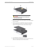
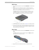
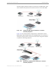
2. Connect A/V cables and control cables as required. The player can
connect to three types of controllers. Refer to cabling instruction for the
M500 Player on page 35.
0 Serial controller (RS-232)
0 Ethernet (TCP/IP)
0 IR controller
Wireless and Powerline Networking
The Kaleidescape server must be connected to the Internet to receive
software updates and updates from the Movie and Music Guides, and to
notify Kaleidescape if service is required.
Although the reliability of a wired Internet connection is preferred, in some
situations the most practical option is an Internet connection using one of
the following technologies:
• Wireless LAN
• Powerline communication
Wireless networks use radio frequencies to communicate without wires.
Powerline networks carry data over a conductor also used for electric power
transmission.
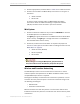
When picking up or moving the Mini System, grasp the bottom of
the system with two hands. Do NOT lift by the plastic side panels.