
Installation guide

Kaleidescape Part No. 101-0105-00 Rev 3 Page 36
Kaleidescape Installation Guide Physical Installation
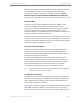
a. Connecting to a serial controller
The M500 player acts as standard Data Terminal Equipment (DTE)
with an RS-232 serial controller, connected via a female–female
DB-9 serial cable.
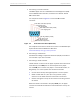
Use the pinout shown in Figure 3-9 to wire the DB-9 female
connector.
Figure 3-9 Serial Control Port Pinout (Male DB-9)
For complete instructions for serial control, refer to the Kaleidescape
System Control Protocol Reference Manual at
www.kaleidescape.com/go/control-protocol.
b. Connecting to the Ethernet
No additional cabling is required for Ethernet (TCP/IP) controllers if
the controller is part of the network.
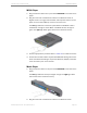
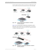
c. Connecting to an IR controller
The IR receiver on the front of the player is paired with an IR emitter
wired directly to the
IR-IN
port on the back panel of the player.
Use the
IR-IN
port to connect the player to a remote IR receiver, an
RF gateway, or a control system that sends IR commands.
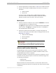
0 Cut the emitter off any existing IR repeater or control system.
0 Solder a cable with an 1/8 in. (3.5 mm) tip-sleeve (mono)
connector to the leads that were connected to the emitter.
0 Connect the signal to the tip of the connector and the ground to
the sleeve.
When this cable is connected to the player
IR-IN
port, the player
receives the same IR commands that would have been sent by the
emitter.
1 DCD Data carrier detect (unused)
2 RD Receive data
3 TD Transmit data
4 DTR Data terminal reach (unused)
5 SG Signal ground
6 DSR Data set ready (unused)
7 RTS Request to send
8 CTS Clear to send
9 RI Ring indicator (unused)