
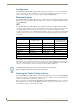
Specifications

Installation
23
MXD/T-1000 10.1" Modero® X Series Touch Panels
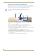
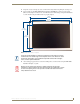
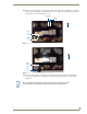
10. Insert each connector into its corresponding location along the back of the device (FIG. 17). To reach the
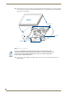
RJ45 connector, gently pull it from beneath the electronics cover (FIG. 18). Attach the Ethernet cable and
gently push the connection back under the cover.
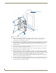
11. Test the incoming wiring by attaching the panel connections to their terminal locations and applying
power. Verify that the panel is receiving power and functioning properly to prevent repetition of the
installation.
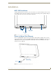
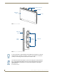
FIG. 17 Rear of the MXD-1000 (Portrait)
FIG. 18 Rear of the MXD-1000 (detail of the RJ45 connection)
RJ45
Port
USB
Port
Micro-USB
Port
Top
RJ45
cable
clip
RJ45
Cable
Clip
RJ45
Port
Top
Do not disconnect the connectors from the touch panel. The unit must be installed
with the attached connectors before being inserted into the mounting surface.