
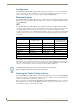
Specifications

Installation
18
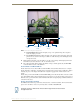
MXD/T-1000 10.1" Modero® X Series Touch Panels
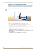
Ethernet Cable Installation and Modification
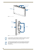
In installations where you wish to conceal the Ethernet cable, a hole at least 1.00” (2.54 cm) in diameter is
required in the surface to allow passage of the female RJ45 connector (FIG. 11). If using a smaller hole is
unavoidable, you will need to disconnect the Ethernet cable (ECA5968-05) from the device.
To disconnect and reconnect the MXT-1000’s Ethernet cable to allow use of a hole smaller than 1.00” in
diameter:
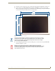
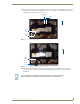
1. On a soft surface, turn the MXT-1000 face-down to access the bottom of the device.
2. Remove the clamp holding the Ethernet cable (FIG. 11) until the Ethernet cable moves freely.
3. Remove the Ethernet cable connector and pull the cable out of the clamp.
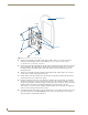
4. Pass the Ethernet cable (ECA5968-05) through the hole, with the RJ45 connector on the other side of the
installation surface from the device.
5. Press the Ethernet cable back into the clamp. Do NOT tighten the clamp at this time.
6. Using a nonconductive item such as a wooden stick, reinsert the Ethernet cable connector into the device.
Use the stick to ensure that the connector is properly seated.
7. Tighten the clamp to secure the Ethernet cable. Make sure the clamp is around the bundled black cable,
not the individual wires
8. Connect the RJ45 connector to its incoming Ethernet cable and apply power.
The minimum diameter hole through which the Ethernet cable may pass is 0.50"
(1.27 cm).
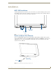
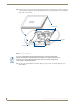
FIG. 11 Bottom of the MXT-1000
Ethernet Cable
Connector
Clamp
MXT-1000