Operation/Reference Guide DAS-SIRIUS SIRIUS© Tuner Module for Mi-Series Audio Controllers Matrix Distributed Audio Initial Release:7/21/2008
AMX Limited Warranty and Disclaimer All products returned to AMX require a Return Material Authorization (RMA) number. The RMA number is obtained from the AMX RMA Department. The RMA number must be clearly marked on the outside of each box. The RMA is valid for a 30-day period. After the 30-day period the RMA will be cancelled. Any shipments received not consistent with the RMA, or after the RMA is cancelled, will be refused. AMX is not responsible for products returned without a valid RMA number.
Table of Contents Table of Contents DAS-SIRIUS Tuner Module ..................................................................................1 Overview .................................................................................................................. 1 Installation ................................................................................................................ 1 Setting the Jumpers .............................................................................................
Table of Contents SIRIUS – Tactile Keypad ....................................................................................21 SIRIUS Source Control............................................................................................. 21 SIRIUS Messages ...............................................................................................23 Overview ................................................................................................................ 23 SIRIUS ID Display ......
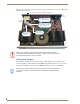
DAS-SIRIUS Tuner Module DAS-SIRIUS Tuner Module Overview Add Sirius satellite radio functionality to your AMX Distributed Audio system with the DAS-SIRIUS Satellite Radio Tuner Module (FG1110-02). Tuner Jumpers Tuner Mounting Plate 20-pin Tuner Ribbon Cable connector SIRIUS Antenna connector FIG. 1 DAS-SIRIUS Satellite Radio Tuner Module “SIRIUS”, the SIRIUS dog logo, and channel names and logos are trademarks of SIRIUS Satellite Radio Inc. All rights reserved.
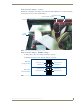
DAS-SIRIUS Tuner Module FIG. 2 provides orientation for the various internal components that must be accessed to install the Tuner Module and set the Jumpers. Tuner slots (Top = Position 1, Bottom = Position 2) rear panel Rear-Board Pin Bus (Controller Jumpers) Tuner Modules Tuner Module Jumpers (located behind ribbon cable connector) 20-pin Tuner Ribbon Cable connector 20-pin Tuner Ribbon Cable front FIG.
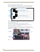
DAS-SIRIUS Tuner Module Audio Controller Jumpers - Location Examine the configuration of the jumpers on the left-side Rear-Board Pin Bus, as seen when viewing the rear board from the front of the Controller (FIG. 3). Rear-Board Pin Bus Audio Controller Jumpers rear panel Tuner Modules FIG. 3 Audio Controller - Rear-Board Pin Bus / Jumpers Audio Controller Jumpers - ON/OFF Settings ON position = pins 3 and 2 jumpered (with pin 1 exposed). OFF position = pins 2 and 1 jumpered (with pin 3 exposed).
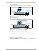
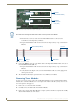
DAS-SIRIUS Tuner Module Audio Controller Jumpers - Dual Tuner Setting With the DAS-AMFM Tuner Module installed in position 1, and the DAS-SIRIUS Tuner Module installed in position 2, the Audio Controller jumpers should all be set to ON, as shown in FIG. 5: Top Left of Rear-Board Pin Bus 3 TUNER 1 Jumpers 1 3 Tuner 1 jumpers (in ON position) 1 3 TUNER 2 Jumpers 3 1 Tuner 2 jumpers (in ON position) 1 FIG.
DAS-SIRIUS Tuner Module Tuner 1 Jumper Settings The Tuner Module installed in position 1 must be set to Tuner 1, as shown in FIG. 7: TUNER 1 Jumpers TUNER 1 Jumpers TUNER 2 Jumpers TUNER 2 Jumpers FIG. 7 Tuner Module - Tuner 1 Jumper Configuration Tuner 2 Jumper Settings The Tuner Module installed in position 2 must be set to Tuner 2, as shown in FIG. 8: TUNER 1 Jumpers TUNER 1 Jumpers TUNER 2 Jumpers TUNER 2 Jumpers FIG.
DAS-SIRIUS Tuner Module Position 1 (DAS-AMFM installed) TUNER 1 Position 2 (Tuner Option cover plate) TUNER 2 FIG. 9 Rear Panel Tuner with Tuner Option cover plate Be careful not to damage the white ribbon cable on the top of the Tuner Module. The Rear Panel connector at the end of the Tuner Ribbon Cable is connected to the Controller’s rear board pin-bus (see FIG. 2). Keep the Tuner Ribbon Cable oriented so that the red stripe is always on top, as indicated in FIG.
DAS-SIRIUS Tuner Module rear of Controller (side view,) DAS-AMFM DAS-SIRIUS Tuner 1 connector (to DAS-AMFM Module) Tuner 2 connector (to DAS-SIRIUS Module) Tuner Ribbon Cable FIG. 11 Tuner 1 / 2 Module Connections (side view of Controller) 4. To remove TUNER 1, place the TUNER 1 Audio Controller jumpers in the OFF position (FIG. 12). Top Left of Rear-Board Pin Bus 3 TUNER 1 Jumpers 3 1 Tuner 1 jumpers (in OFF position) 1 FIG. 12 Audio Controller Jumper Configuration (No TUNER 1) 5.
DAS-SIRIUS Tuner Module Connecting and Positioning the SIRIUS Antenna 1. Connect the provided SIRIUS Antenna to the DAS-SIRIUS (see FIG. 1). 2. Verify the Signal strength a. Access the programming menus via the front of the Controller. b. Select Setup\SIRIUS. c. Select "Status". In this menu, you can check the following: "ANT = Antenna Status" "ACT = Activation Status" "SAT = Satellite Signal" "TER - Terrestrial Signal" d. Select "SAT" to determine the Satellite Signal Strength.
Mi Series – SIRIUS Setup screen Mi Series – SIRIUS Setup screen Accessing the SIRIUS Setup Screen 1. To access the SIRIUS menus on the Controller, press the SELECT button on the front of the Controller. The following screen will be displayed (FIG. 14): FIG. 14 Mi Series Controller - Main Menu 2. Select Setup to display the System Setup Mode screen. If an on-board DAS-SIRIUS module is detected, SIRIUS is displayed on this screen. 3. Select SIRIUS (FIG. 15). FIG.
Mi Series – SIRIUS Setup screen SIRIUS Setup 1. When SIRIUS is selected, the SIRIUS Setup screen is displayed (FIG. 17): Exit SIRIUS Setup Status SIRIUS ID Channel Category FIG. 17 SIRIUS Setup screen The options on this page are described in the following sub-sections: SIRIUS Setup - CAT Selecting CAT (Category) displays the following screen (FIG. 18), where the Category can be selected by choosing PREV/NEXT. The default = 1 All. FIG.
Mi Series – SIRIUS Setup screen Presets can be set via this screen if the installer chooses. There are 10 available preset positions. Presets can also be set at the keypad. SIRIUS Setup - ID Selecting ID displays the SIRIUS ID (FIG. 20). FIG. 20 SIRIUS ID screen SIRIUS Setup - Status Selecting STATUS will display the following SIRIUS status screen (FIG. 21): Exit SIRIUS Setup Terrestrial Signal Level Satellite Signal Level Activation Status Antenna Status FIG.
Mi Series – SIRIUS Setup screen 12 DAS-SIRIUS Sirius Tuning Module for Mi-Series Audio Controllers
Controlling SIRIUS via the LCD Keypad Controlling SIRIUS via the LCD Keypad Overview The LCD keypad is a full touch screen keypad with two tactile buttons that are used for Volume UP/DOWN. There are 3 LCD screens for the SIRIUS Source (FIG. 22): • HOME screen User can select any of the available sources • MAIN screen Displays metadata, including: Channel #, Channel Name, Artist, Song Title & Composer and any SIRIUS messages.
Controlling SIRIUS via the LCD Keypad Selecting SIRIUS as the Audio Source On the Home screen, SIRIUS will appear in the top left touch field and is considered to be Source 1 (FIG. 23). Select SIRIUS (Source 1) FIG. 23 LCD Keypad - Home screen To turn ON the SIRIUS source, touch the text “SIRIUS”. The screen will change to the SIRIUS Main Screen and the > icon appears in front of the text to indicate that SIRIUS is ON in that room. Volume UP to the desired volume level.
Controlling SIRIUS via the LCD Keypad Display Line #1 Channel # & Channel Name Channel # + Channel Name will be displayed up to a max. of 14 characters. This display line scrolls once and stops. Touch the line of text to update the text and scroll the info once. Display Line #2 Artist Name, Song Title & Composer The Artist, Song Title & Composer are displayed up to a max. of 14 characters. This display line scrolls once and stops. Touch the line of text to update the text and scroll the info once.
Controlling SIRIUS via the LCD Keypad SIRIUS NUMERIC screen Touching NUMERIC on the SIRIUS SAT Main screen (FIG. 24 on page 14) displays the standard Numeric screen where the user can directly key in the Channel of their choice (FIG. 26). Numeric buttons Use the "point" button to specify channels that use a point in their channel number (Ex: 90.1) Selects the channel FIG. 26 LCD Keypad - SIRIUS NUMERIC screen Press the numeric buttons to specify a channel number, and press Enter to select.
Controlling SIRIUS via the LCD Keypad SIRIUS MORE>> screen Touch MORE on the SIRIUS SAT Main screen (FIG. 24 on page 14) to display the SIRIUS MORE screen (FIG. 27). List Channels Set Presets List Categories Set Favorites Return to the SIRIUS SAT Main screen FIG. 27 LCD Keypad - SIRIUS MORE screen The options on this screen allow the user to perform the following: List Channels List Categories Set Presets Set Favorites List - Channels Touch CH LIST on the SIRIUS MORE screen (FIG.
Controlling SIRIUS via the LCD Keypad To scroll through the channels, touch “SCROLL +” or “SCROLL –”. When scrolling, up to 3 channels will be displayed Touch any channel to select it. When the Channel is selected: The SIRIUS MAIN screen is displayed & the Channel selected begins playing. The Channel #, Channel Name, Artist, Song Title and Composer are displayed. List - Category Touch CAT on the SIRIUS MORE screen (FIG.
Controlling SIRIUS via the LCD Keypad SIRIUS - Presets Users can set up to 10 presets per source. 1. From the SIRIUS More screen (FIG. 27 on page 17), touch PRESET, to access the Numeric screen (FIG. 30). Key in a channel that you want to set a Preset for, using the Numeric buttons Use the "point" button to specify channels that use a point in their channel number (Ex: 90.1) Selects the channel FIG. 30 LCD Keypad - SIRIUS Presets screen 2. Use the numeric buttons to key in the Channel. 3.
Controlling SIRIUS via the LCD Keypad SIRIUS - Favorites Favorites is a standard functionality of the Matrix Controller and is available for all sources. One minute after an “ALL OFF” has been performed, or 10 Minutes after every zone/room has been turned off, the controller will send a Power OFF command to all sources. The first time a source is turned on in any room (after a system power off), if a favorite has been set for that room and that source, the favorite station/channel will begin playing.
SIRIUS – Tactile Keypad SIRIUS – Tactile Keypad FIG. 32 shows the navigation button layout for Tactile Keypads. Nav Up Nav Left Nav Right Nav Down FIG. 32 Tactile Keypad SIRIUS Source Control When the Source type = SIRIUS, the navigation buttons perform the following functions: NAV UP NEXT Channel/Station (Ch 9, 10, 11 etc.) NAV DOWN PREV Channel/Station (Ch 9, 8, 7 etc.
SIRIUS – Tactile Keypad 22 DAS-SIRIUS Sirius Tuning Module for Mi-Series Audio Controllers
SIRIUS Messages SIRIUS Messages Overview Messages specific to the DAS-SIRIUS tuner module that can be displayed on the Controller or LCD Keypad include: Loss of Signal: “Acquiring Signal” Antenna Error: “Antenna Error” Subscription Updates: “Subscription Updated” Channel Map Updates: “Updating Channels” Invalid Channel: “Invalid Channel” Unsubscribed Channel: “CALL 888-539-SIRIUS TO SUBSCRIBE” When first powering ON the Controller, and the user selects the SIRIUS source, the Initializing SIRIUS
SIRIUS Messages 24 DAS-SIRIUS Sirius Tuning Module for Mi-Series Audio Controllers
SIRIUS Messages DAS-SIRIUS Sirius Tuning Module for Mi-Series Audio Controllers 25
AMX. All rights reserved. AMX and the AMX logo are registered trademarks of AMX. AMX reserves the right to alter specifications without notice at any time. ©2007 7/08 It’s Your World - Take Control™ 3000 RESEARCH DRIVE, RICHARDSON, TX 75082 USA • 800.222.0193 • 469.624.8000 • 469-624-7153 fax • 800.932.6993 technical support • www.amx.