Instruction Manual Modero S Series Touch Panels MST-1001/MSD-1001-L - 10.1" Modero S Series Touch Panels MST-701/MSD-701-L - 7" Modero S Series Touch Panels MST-431/MSD-431-L - 4.
AMX Limited Warranty and Disclaimer This Limited Warranty and Disclaimer extends only to products purchased directly from AMX or an AMX Authorized Partner which include AMX Dealers, Distributors, VIP’s or other AMX authorized entity.
Table of Contents Table of Contents Modero S Series G4 Touch Panels ......................................................................1 Overview .................................................................................................................. 1 Features .......................................................................................................................... 1 Sleep Button .................................................................................................
Table of Contents Installing Wall-Mount (MXD) Panels ..................................................................27 A Note About Wall and Rack Installation................................................................ 27 Installation Recommendations....................................................................................... 28 MSD-1001/701/431-L ............................................................................................. 28 Removing the Backbox .........................
Modero S Series G4 Touch Panels Modero S Series G4 Touch Panels Overview The Modero S Series is a beautiful touch panel family sophisticated enough for room control yet priced right for the most cost sensitive installations. The Modero S Series panels include VoIP, brilliant 24-bit color depth, PoE connectivity, USB and streaming video.
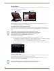
Modero S Series G4 Touch Panels Sleep Button S Series touch panels are operated using an integral touchscreen, as well as the Sleep button. The Sleep button is located on the top center edge of the panel (see FIG. 2). Sleep button (on top panel) Sleep button (on top panel) FIG. 2 Sleep Button location - Tabletop and Wall Mount If the device has gone into its Sleep Mode, touching the touchscreen or pressing the Sleep button will reactivate it. Press and hold the Sleep button to access the Settings menu.
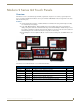
Modero S Series G4 Touch Panels Bluetooth Support S Series touch panels allow the use of Bluetooth keyboard and mouse combinations, using HID Profile v1.1. Using a keyboard and mouse with the device requires use of the MXA-BT Bluetooth USB Adapter (FG5968-19). Picture View By connecting a USB drive via one of the device’s USB ports, Picture View allows the S Series panel to access JPEG images on that drive and display them on the touchscreen.
Modero S Series G4 Touch Panels 5. On the rightmost red button, select the number of seconds a selected image will be displayed in Picture View. This may be selected between 5, 10, 15, 30, and 60 seconds. 6. The counter beneath the buttons displays the number of images currently uploaded by the MST-1001 versus the number detected on the USB drive. Preview Mode and Normal Mode Picture View has two modes: Preview Mode and Normal Mode. Preview Mode allows the user to configure Picture View.
Modero S Series G4 Touch Panels If the calibration was improperly set and you cannot return to the Calibrate page (through the panel’s firmware); this firmware page can be accessed via G4 WebControl by navigating to the Protected Setup page and pressing the Calibrate button through the VNC window. This action causes the panel to go to the Calibrate page seen above, where recalibration of the actual touch panel can be performed again using the above procedures.
Modero S Series G4 Touch Panels 6 Modero S Series G4 Touch Panels Instruction Manual
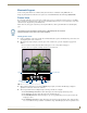
MST/D-1001 - 10.1" S Series Touch Panels MST/D-1001 - 10.1" S Series Touch Panels MST-1001 (Tabletop) Microphone Sleep Button USB Port FIG. 6 MST-1001 MST-1001 Specifications MST-1001 Specifications DIMENSIONS (HWD) 6 13/16" x 10 1/16" x 2" (174mm x 255mm x 51mm) WEIGHT 2.6 lbs (1.179 Kg) POWER CONSUMPTION • • • • • EXTERNAL POWER SUPPLY REQUIRED Optimal performance requires use of one of the following AMX PoE power supplies (not included): Full-On: 14 W (max) Typical: 7.5 W Standby: 4.
MST/D-1001 - 10.1" S Series Touch Panels MST-1001 Specifications (Cont.) TOUCH SCREEN DISPLAY • Display Type: TFT Active Matrix Color LCD • Display Size (WH): Landscape: 9.1" x 5.9" (230 mm x 149 mm), 10.8" (274 mm) diagonal • Viewable Area (WH): Landscape: 8.5" x 5.4" (217 mm x 136 mm ), 10.0" (256 mm) diagonal • Resolution: Landscape: 1280x800 • Aspect Ratio: Landscape: 16:9 • Brightness: 350 cd/m2 • Contrast Ratio: 800:1 • Color Depth: 16.
MST/D-1001 - 10.1" S Series Touch Panels MST-1001 Specifications (Cont.) ENVIRONMENTAL • • • • • Temperature (Operating): 32° F to 104° F (0° C to 40° C) Temperature (Storage): 4° F to 140° F (-20° C to 60° C) Humidity (Operating): 20% to 85% RH Humidity (Storage): 5% to 85% RH Power ("Heat") Dissipation: On: 109.2 BTU/hr Standby: 10.6 BTU/hr INCLUDED ACCESSORIES • MXA-USB-C, USB Port Cover Kit, Modero X Series Touch Panel (FG5968-18) • Cat5e Ethernet Cable, Flat Black (ECA2265-10) • UTP CAT.
MST/D-1001 - 10.1" S Series Touch Panels MSD-1001-L Specifications (Cont.) EXTERNAL POWER SUPPLY REQUIRED Optimal performance requires use of one of the following AMX PoE power supplies (not included): • PS-POE-AF-TC, PoE Injector, 802.
MST/D-1001 - 10.1" S Series Touch Panels MSD-1001-L Specifications (Cont.
MST/D-1001 - 10.
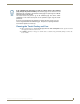
Modero S Series G4 Touch Panels Instruction ManualMST/D-701 - 7" S Series Touch Panels MST/D-701 - 7" S Series Touch Panels MST-701 (Tabletop) Microphone Sleep Button USB Port FIG. 8 MST-701 MST-701 Specifications MST-701 Specifications DIMENSIONS (HWD) 4 1/2" x 7 3/8" x 3 3/16" (115 mm x 188 mm x 81 mm) WEIGHT 1.4 lbs (.635 Kg) POWER CONSUMPTION • Full-On: 13 W • Typical: 7 W • Standby: 4.5 W • Shutdown: 0.
MST/D-701 - 7" S Series Touch Panels MST-701 Specifications (Cont.) TOUCH SCREEN DISPLAY • Display Type: TFT Active Matrix Color LCD with Fringe Field Switching (FFS) - Wide viewing angle technology • Display Size (WH): Landscape: 7.3" x 4.8" (186 mm x 122 mm), 8.8" (222 mm) diagonal • Viewable Area (WH): Landscape: 6.05" x 3.54" (154 mm x 90 mm), 7.0" (178 mm) diagonal • Resolution: Landscape: 1024x600 • Aspect Ratio: Landscape: 16:9 • Brightness: 400 cd/m2 • Contrast Ratio: 800:1 • Color Depth: 16.
Modero S Series G4 Touch Panels Instruction ManualMST/D-701 - 7" S Series Touch Panels MST-701 Specifications (Cont.) ENVIRONMENTAL • Temperature (Operating): 32° F to 104° F (0° C to 40° C) • Temperature (Storage): 4° F to 140° F (-20° C to 60° C) • Humidity (Operating): 20% to 85% RH • Humidity (Storage): 5% to 85% RH • Power ("Heat") Dissipation: On: 27.3 BTU/hr Standby: 10.
MST/D-701 - 7" S Series Touch Panels MSD-701-L Specifications (Cont.) POWER CONSUMPTION • Full-On: 11 W • Typical: 7.5 W • Standby: 4.5 W • Shutdown: 0.7 W • Start-Up Inrush Current: Not applicable due to PoE standard EXTERNAL POWER SUPPLY REQUIRED Optimal performance requires use of one of the following AMX PoE power supplies (not included): • PS-POE-AF-TC, PoE Injector, 802.
Modero S Series G4 Touch Panels Instruction ManualMST/D-701 - 7" S Series Touch Panels MSD-701-L Specifications (Cont.) AUDIO • Microphone: -42 dB ±3 dB sensitivity FET microphone • Speakers: 4 ohm, 1.5 Watt, 500 Hz cutoff frequency • Supported Audio Codecs: MP2 Layer I and II, MP3 (8 kHz, 11.025 kHz, 12 kHz, 16 kHz, 22.05 kHz, 24 kHz, 32 kHz, 44.1 kHz, 48 kHz) AAC-LC (8 kHz, 96 kHz) G.
MST/D-701 - 7" S Series Touch Panels 18 Modero S Series G4 Touch Panels Instruction Manual
MST/D-431 - 4.3" S Series Touch Panels MST/D-431 - 4.3" S Series Touch Panels MST-431 (Tabletop) Sleep Button Microphone USB Port FIG. 10 MST-431 MST-431 Specifications MST-431 Specifications DIMENSIONS (HWD) 3 1/4" x 5 1/16" x 3 1/8" (82 mm x 128 mm x 79 mm) WEIGHT 0.9 lbs (.4 Kg) POWER CONSUMPTION • Full-On: 4 W • Typical: 3 W • Standby: 2 W • Shutdown: 0.
MST/D-431 - 4.3" S Series Touch Panels MST-431 Specifications (Cont.) TOUCH SCREEN DISPLAY • Display Type: TFT Active Matrix Color LCD • Display Size (WH): Landscape: 5" x 3.4" (128 mm x 87 mm), 6" (152 mm) diagonal • Viewable Area (WH): Landscape: 3.7" x 2.1" (95 mm x 54 mm), 4.3" (109 mm) diagonal • Resolution: Landscape: 480x272 • Aspect Ratio: Landscape: 16:9 • Brightness: 350 cd/m2 • Contrast Ratio: 600:1 • Color Depth: 16.
MST/D-431 - 4.3" S Series Touch Panels MST-431 Specifications (Cont.) INCLUDED ACCESSORIES • MXA-USB-C, USB Port Cover Kit, Modero X Series Touch Panel (FG5968-18) • Cat5e Ethernet Cable, Flat Black (ECA2265-10) • UTP CAT.5E Snap In Coupler, Black (64-5968-01) OPTIONAL ACCESSORIES • MSA-STMK-43, Secure Table Mount Kit for 4.3" Modero S Tabletop Touch Panel (FG2265-18) • PS-POE-AF-TC, PoE Injector, 802.
MST/D-431 - 4.3" S Series Touch Panels MSD-431-L Specifications (Cont.) CERTIFICATIONS • FCC Part 15 Class B • CE EN 55022 • CE EN 55024 • CE EN 60950-1 • IEC 60950-1 • C-Tick CISPR 22 Class B • IC CISPR 22 Class B • UL 60950-1 • VCCI CISPR 22 Class B • RoHS • WEEE TOUCH SCREEN DISPLAY • Display Type: TFT Active Matrix Color LCD • Display Size (WH): Landscape: 5" x 3.4" (128 mm x 87 mm), 6" (152 mm) diagonal • Viewable Area (WH): Landscape: 3.7" x 2.1" (95 mm x 54 mm), 4.
MST/D-431 - 4.3" S Series Touch Panels MSD-431-L Specifications (Cont.) FRONT PANEL COMPONENTS • Sleep Button: Sleep button to activate sleep mode and power off. Also provides access to setup pages (can be disabled) • Programmable Red/Green LEDs: Programmable red/green LED in the front, left and right sides of the panel, LEDs are beautifully recessed and nearly invisible when not lit CONNECTIONS • Ethernet: 10/100 Auto MDI-X port, RJ-45 connector • USB: (1) USB host 2.
MST/D-431 - 4.
Installing Tabletop (MXT) Panels Installing Tabletop (MXT) Panels MST-1001/701/431 Detailed specifications drawings for the MST-1001 are available to download from www.amx.com. Detailed specifications drawings for the MST-701 are available to download from www.amx.com. Detailed specifications drawings for the MST-431 are available to download from www.amx.com. Connector Locations USB peripherals (mouse, keyboard, etc.) may be connected to the USB port on the rear of the device.
Installing Tabletop (MXT) Panels 26 Modero S Series G4 Touch Panels Instruction Manual
Installing Wall-Mount (MXD) Panels Installing Wall-Mount (MXD) Panels A Note About Wall and Rack Installation AMX DEVICE Some products are installed in areas of differing temperature and cooling methodologies. These include products installed in walls, racks, cabinets, etc. Those areas may have different temperatures and/or cooling approaches that must be taken into consideration to maintain the product within the specified operating temperature. FIG.
Installing Wall-Mount (MXD) Panels Installation Recommendations During any installation, a lack of ventilation may produce conditions that may adversely affect the device’s operation. In these circumstances, special care must be made to make sure that temperatures within enclosed areas do not exceed the device’s maximum rated temperature.
Installing Wall-Mount (MXD) Panels Removing the Backbox S Series touch panels are shipped pre-installed in a plastic Backbox. This Backbox must be detached from the panel before installation. Also, after installation there are circumstances (such as firmware updates or other maintenance) that will require accessing the device’s Micro-USB ports. In these cases, the panel may need to be removed from the Backbox.
Installing Wall-Mount (MXD) Panels Installation Refer to A Note About Wall and Rack Installation on page 27 for important notes on thermal concerns with Wall and Rack Installations. S Series touch panels may be installed directly into a solid surface environment, using either solid surface screws or the included locking tabs for different mounting options. Once installed, the panel is contained within a clear outer housing known as the Backbox (FIG. 16).
Installing Wall-Mount (MXD) Panels Installing the S Series Panel into a Wall S Series touch panels come with a clear plastic Backbox designed to attach the panel to most standard wall materials. This Backbox has locking tabs to help lock the Backbox to the wall (see FIG. 16). These locking tabs are only extended AFTER the Backbox is inserted into the wall. When installing the Backbox, make sure that the assembly is in the correct position and in the correct place.
Installing Wall-Mount (MXD) Panels MXD-701-L Dimensions Notes: Dimensions in parenthesis are in millimeters Additional detailed installation and product drawings are available to view/download at www.amx.com FIG.
Installing Wall-Mount (MXD) Panels MXD-431-L Dimensions Notes: Dimensions in parenthesis are in millimeters Additional detailed installation and product drawings are available to view/download at www.amx.com FIG. 19 MSD-431-L In order to ensure a stable installation of the MSD-1001-L, the thickness of the wall material must be a minimum of .50 inches (1.27cm) and a maximum of .875 inches (2.22cm). The mounting surface should also be smooth and flat. Installing the Backbox 1.
Installing Wall-Mount (MXD) Panels MXD-1001-L MXD-701-L MXD-431-L FIG.
Installing Wall-Mount (MXD) Panels Using the included template to select the final placement of the Backbox is highly recommended. The outside edges of the template are the same dimensions as the touch panel, which allows you to troubleshoot possible conflicts with wall edges, doors, and other potential obstacles. 3. After ensuring proper placement, cut out the mounting surface for the Backbox, using the MSD-1001-L Installation Template as a guide.
Installing Wall-Mount (MXD) Panels The maximum recommended torque to screw in the locking tabs on the plastic Backbox is 5 IN-LB [56 N-CM]. Applying excessive torque while tightening the tab screws, such as with powered screwdrivers, can strip out the locking tabs or damage the Backbox. Not all of the tabs must be extended to lock the Backbox in place, but extending a minimum of the top and bottom tabs is highly recommended.
Installing Wall-Mount (MXD) Panels FIG. 24 shows the connectors on the rear of the MSD-431-L: RJ-45 Port Micro-USB Port FIG. 24 Rear of the MSD-431-L 10. Test the incoming wiring by attaching the panel connections to their terminal locations and applying power. Do not disconnect the connectors from the touch panel. The unit must be installed with the attached connectors before being inserted into the mounting surface.
Installing Wall-Mount (MXD) Panels Removing The Touch Panel From the Backbox After Wall Installation Occasionally it may be necessary to remove the touch panel from the wall to perform routine maintenance, firmware upgrade or troubleshooting. This section describes the best methods for removing to touch panel from the Backbox without damaging either. 1. With fingertips placed on the top edge of the bezel, press down on the panel firmly but gently to unhinge the top clips of the Backbox.
Upgrading Firmware Upgrading Firmware Overview Programming the S Series touch panels require the use of NetLinx Studio and TPDesign4, both available from www.amx.com. Downloading Firmware Updates From www.amx.com Before attempting to upgrade the firmware, you must have the appropriate Kit file for your touch panel: All S Series touch panels share the same firmware. 1. Open the product page for the panel, at www.amx.com (Trade Site). 2.
Upgrading Firmware 2. Create a directory on the USB flash drive with one of the following names, depending on the panel you are upgrading: “MST-1001” or “MSD-1001” “MST-701” or “MSD-701” "MST-431" or "MSD-431" Note that the name must match exactly (do not include the quotes) These directory names are not case-sensitive: 3. Copy the firmware (.kit) file to be transferred (for example, "SW5968_ModeroS_v2_106_08.kit") into this directory on the flash drive. Make sure this is the only .
Upgrading Firmware Upgrading from Previous Firmware S Series panels provide the option to revert the device to the previous firmware run before an upgrade. To upgrade the device from previously loaded firmware: 1. From the Settings page, select the Configuration page. 2. From the Configuration page, select Admin. 3. From the Admin Configuration page, select Install Firmware. 4. In the Firmware Installation page, select Previous. 5. The Confirmation Dialog box (FIG.
Upgrading Firmware Transferring the KIT File via NetLinx Studio 1. In Netlinx Studio, right-click in the Online Tree tab of the Workspace window and select Refresh System Online Tree to refresh the device listing. The touch panel should be indicated in the device list. 2. Right-click on the target panel and select Firmware Transfer to open the Send to NetLinx Device dialog. Alternatively, select Tools > Firmware Transfers > Send To NetLinx Device to open this dialog (FIG. 31): FIG.
Troubleshooting Troubleshooting Overview This section describes the solutions to possible hardware/firmware issues that could arise during the common operation of a Modero S touch panel. Panel Doesn’t Respond to Touches Symptom: The device either does not respond to touches on the touch screen or does not register the touch as being in the correct area of the screen. If the screen is off: The device may be in Display Sleep Mode. Press and hold the Sleep button to wake up the panel.
In the ever-changing AV industry, continual education is key to success. AMX University is dedicated to ensuring that you have the opportunity to gather the information and experience you need to deliver strong AMX solutions. Plus, AMX courses also help you earn CEDIA, NSCA, InfoComm, and AMX continuing education units (CEUs).