
Corporation Control System Accessories Operation/Reference Guide


Installation
11
Anterus RFID Solution
Installation
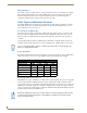
Overview
Installation and configuration of the Anterus solution includes connecting the ANT-RDR Reader to the
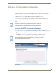
NetLinx Master via AxLink, and using the ANT-RDR’s built-in web interface to name each RFID tag,
and specify communications and security settings.
Connecting the ANT-RDR To a NetLinx Master
The ANT-RDR uses a single 4-pin captive-wire AxLink port to connect the ANT-RDR to a NetLinx
Master, and (optionally) to other ANT-RDRs. To connect the ANT-RDR to the NetLinx Master via
AxLink, install the AXlink data/power bus wiring as shown in FIG. 11.
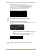
Connecting Additional ANT-RDRs
To connect additional ANT-RDRs to create a RFID Reader Network Group, follow the standard AxLink
bus wiring (FIG. 12).
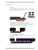
FIG. 10 Basic Anterus System
FIG. 11 AXlink data/power connections
FIG. 12 Connecting Additional ANT-RDRs
NetLinx Master
ANT-RDR Anterus Tags
PWR
AXP
AXM
GND
ANT-RDRNetLinx Master
PWR
AXP
AXM
GND
PWR
AXP
AXM
GND
ANT-RDRNetLinx Master
PWR
AXP
AXM
GND
PWR
AXP
AXM
GND
PWR
AXP
AXM
GND
PWR
AXP
AXM
GND
ANT-RDRANT-RDR ANT-RDR