
Specifications
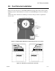

SLC Device Installation
150972 5-13
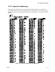
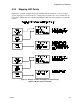
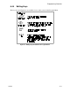
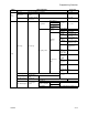
5.10.2 Dipswitch Addressing
Input and relay module addresses are set using the dipswitch that appears on the module
board. The chart below shows the available addresses. For example, to select address 3, place
dipswitches 1 and 2 in the up position. The range of valid addresses is 1-127 (0 is an invalid
address).
Figure 5-15 SLC Device Addressing Using Dipswitches