
Specifications

SLC Device Installation
150972 5-11
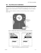
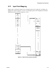
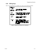
5.9 Duct Detector Installation
Figure 5-12 shows the layout of the SD505-ADH duct housing with a detector base in place,
including location of the terminals for connection to the FACP. Figure 5-13 shows wiring in
detail.
Address the detector head before attaching it to the base. This procedure is explained in
Section 5.10.
Figure 5-12 Model SD505-ADH Internal View Showing Connector Locations
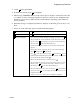
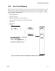
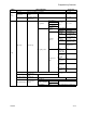
Figure 5-13 Duct Detector Connection to the 5820
Terminals on detector
base are for SLC loop
connection. Make loop
connections below.
not
Exhaust Tube
Inlet Tube
Connect tubes at back of housing.
1
2
5
6
3
4
Connect to
SLC loop.
See Fig. 5
for wiring details.
Pre-wired connections
t
o
duc
t
de
t
ec
t
o
r
base
.
1234
Detector Base