
Specifications


Control Panel Installation
150972 4-45
4.16.3 NFPA 72 Polarity Reversal
When the 5220 is wired and programmed for polarity reversal, it reports alarm and trouble
events to a remote site. Alarms will override trouble conditions and it will not be possible to
reset the remote indicator until the condition is cleared and the 5820 panel is reset.
If an alarm condition occurs, the alarm relay will close, overriding the trouble condition.
To install the 5220 for polarity reversal, follow the steps below:
1. Locate the knockout on the right side of the 5820 cabinet to connect the 5220 using a short
piece of conduit (must not exceed 20 feet in length).
2. Wire the 5220 to the 5820 using the four-wire pigtail provided as shown in Figure 4-43.
This diagram also shows how to connect the 5220 to the remote indicator. Do not install
an EOL resistor in the terminals of the I/O circuit used for this application.
3. Connect earth ground wire to the 5220 chassis with mounting screw.
4. Program the I/O circuit used as continuous and non-silencing. Refer to Section 7.4.1 for
zone grouping and mapping.
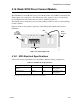
5. If necessary, adjust loop current using the potentiometer (R10) on the 5220 board (see Fig-
ure 4-41). Normal loop current is 2-to-8 mA with a 1k ohm remote station receiving unit.
Maximum loop resistance is 3k ohm.
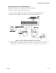
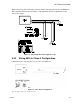
Figure 4-43 Polarity Reversal Connection
All circuits power-limited.
All wiring supervised.
Note:
I/O circuit 1 and Relay 1
used as examples. Any
I/O circuit and either
relay 1 or relay 2 could
be used.
Jumper these terminals
when City Box is not used.