Content Section 1 Introduction .............................................................................................................................................. 1-1 1.1 Overview of Basic System ....................................................................................................................... 1-1 1.1.1 Hardware Features ............................................................................................................................ 1-1 1.1.2 Software Features ...
Content Section 5 SLC Device Installation ............................................................................................................ 5-1 5.1 5.2 5.3 Types of SLC Devices ............................................................................................................................. 5-1 Maximum Number of Devices ................................................................................................................. 5-1 Wiring Requirements for SLC Devices ..........
Content 7.5.1.2 Auto Test Time .................................................................................................................... 7-30 7.5.2 Phone Lines ..................................................................................................................................... 7-30 7.5.2.1 Dialing Prefix ....................................................................................................................... 7-31 7.5.2.2 Number of Answer Rings .......................
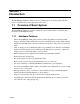
Section 1 Introduction The IntelliKnight 5820 Fire Alarm Control / Communicator is an analog addressable fire control system that meets the requirements of UL 864. 1.1 Overview of Basic System The IntelliKnight 5820 base system is packaged as an assembled stack of 3 circuit boards mounted to an aluminum housing. 1.1.1 Hardware Features • The basic IntelliKnight 5820 panel contains one SLC (Signaling Line Circuit) which supports 127 analog addressable devices (points).
Introduction 1.3 Compatible Products The chart below lists the products available from Silent Knight for use with the IntelliKnight 5820. Model Description SLC Devices SD500-AIM Contact Monitor Module (switch input). Standard size. (This device replaces Model SD500-FRCM-4. See Note below.) SD500-MIM Mini Contact Monitor Module (switch input). Small size. (This device replaces Model SD500-FRCM. See Note below.) SD500-ARM Relay Module (This device replaces Model SD505-ARM. See Note below.
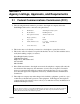
Section 2 Agency Listings, Approvals, and Requirements 2.1 Federal Communications Commission (FCC) 1. The following information must be provided to the telephone company before the IntelliKnight 5820 can be connected to the phone lines: A Manufacturer: Silent Knight Security Systems B Model Number: IntelliKnight 5820 C FCC registration number: AC6USA-23901-AL-E Ringer equivalence: 0.
Section 3 Before You Begin Installing This section of the manual is intended to help you plan your tasks to facilitate a smooth installation. Please read this section thoroughly, especially if you are installing a 5820 panel for the first time. 3.
Before You Begin Installing Table 3-1: Terminal Strip Description and Electrical Rating Rating Terminal # and Label Description Voltage 3.
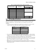
3.5 Board Assembly Diagram Figure 3-2 Model 5820 Assembly Figure 3-2 shows the circuit boards, metal housing and annunciator that attach the 5820 assembly to the cabinet. If you should need to remove the board assembly for repair, remove the four mounting nuts which hold the assembly in the cabinet. Then lift the entire assembly out of the cabinet. Do not attempt to remove the circuit boards from the metal bracket.
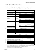
Before You Begin Installing 3.6.2 Current Draw Worksheet Use the worksheet beginning on the next page to determine current requirements during alarm/battery standby operation. (Copy the page if additional space is required.) Table 3-2: Current Draw Calculations Device For each device use this formula: IntelliKnight 5820 Fire Panel (Current draw from battery) # of Devices This column 1 Addressable Devices (381 max.) 5815 SLC Expander (2 max.) 5860 Remote Fire Alarm Annunciator (8 max.
Before You Begin Installing 3.7 Installation Tasks Overview This section of the manual is a chart listing tasks that need to be performed when installing the IntelliKnight 5820 system. The chart is intended to be a handy way for you to make sure you have completed all necessary tasks. Unless noted, these tasks do not have to be performed in the order they are listed here. Important: Connect and address SLC devices before running JumpStart. Task See Sec. (for more info.
Before You Begin Installing Task See Sec. (for more info.) Addressable relay modules U Assign addressable relay modules to output groups through programming. (JumpStart assigns all relay modules to Group 1.) 7.4 LED output points (from the 5880 LED Driver or 5865/66 LED Annunciator) U Assign LED modules to output groups through programming. 7.4.3 All output circuits (1-8): U U Disable (set to UNUSED) any unused circuits.
Section 4 Control Panel Installation Caution! To avoid the risk of electrical shock and damage to the unit, power should be OFF at the control panel while installing or servicing. 4.1 Mounting the 5820 Cabinet Read the environmental specifications in Section 3.2 before mounting the 5820 cabinet. This will ensure that you select a suitable location. The panel should be accessible to main drop wiring runs.
Control Panel Installation 4.3 Battery Connection The 5820 battery charge capacity is 7.0 to 33.0 AH. Use 12V batteries of the same AH rating. Determine the correct AH rating as per your current load calculation (see Section 3.6). Wire batteries in series to produce a 24-volt equivalent. Do not parallel batteries to increase the AH rating.
Control Panel Installation 3. Run extended battery cable from 5820 cabinet through conduit to AB-33 cabinet. See Figure 4-5. AB-33 Cabinet Cover Screws Conduit Coupler Conduit + - + - AB-33 Cabinet Cover Screws Figure 4-5 Battery Connections in the AB-33 Cabinet Note: Any one of the cabinet knock-outs (on either the 5820 or the AB-33 cabinet), that are not previously being used may be utilized to connect conduit between the two cabinets. 4. Connect battery leads to the backup battery terminals.
Control Panel Installation These cases are marked in the chart with an asterisk (*). Maximum length can never be more than 6,000 feet, regardless of gauge used. (The formula used to generate this chart is shown in the note below). Table 4-1: Wire Distances Per Wire Gauge Wiring Distance: SBUS Modules to Panel Total Worst Case Current Draw (amps) 22 Gauge 18 Gauge 16 Gauge 14 Gauge 0.100 1852 ft. 4688 ft. * 6000 ft. * 6000 ft. 0.200 926 ft. 2344 ft. 3731 ft. 5906 ft. 0.300 617 ft. 1563 ft.
Control Panel Installation 4.4.2 Wiring Configurations Figure 4-7 illustrates Class A wiring configuration and Figure 4-8 illustrates Class B configuration.
Control Panel Installation 4.5.1 Mounting the 5860 This section of the manual describes mounting the remote annunciator. The annunciator can be flush- or surface-mounted. Figure 4-10 shows the parts of the annunciator. Instructions for disassembling and mounting appear on the following pages.
Control Panel Installation Flush Mounting with an Electrical Box The 5860 annunciator can be used with the following types of electrical boxes: 4S, singlegang, and double-gang. If an electrical box is used, the box must be 1-3/8” back from the face of the wall to accommodate the annunciator. Studs used with an electrical box must be two by fours (or larger). Figure 4-12 Placement of Electrical Box for Flush Mounting Flush Mounting Steps 1.
Control Panel Installation 4.5.2 5860 Connection to the Panel Connect the 5860 to the panel as shown in Figure 4-14.
Control Panel Installation 4.6.1 5815 Connection to the Panel Connect the 5815 to the IntelliKnight 5820 panel as shown in Figure 4-16. After the 5815 is connected to the panel, it must be added to the 5820 system. This programming step is described in Section 4.10.
Control Panel Installation M odel 5824 (w ith housing) To P arallel P rin ter To S erial P rinter Figure 4-18 Printer Connection 4.7.1 Selecting 5824 Options Configuring the 5824 includes the following steps: • Add the module to the system. JumpStart will add the module automatically (see Section 6.1). You can also add it manually (see Section 4.10). • Select a name, if desired (see Section ). • Select options for the printer and the output port. See below. Printer and Output Port Options 1.
Control Panel Installation 4.8 5880 LED Driver Module The 5880 is an LED driver board that can be used in a wide variety of applications, including as an interface with most customized floor plan annunciator boards. The 5880 can drive up to 40 LEDs and has one PZT controller. The 5880 also has eight inputs for dry contact monitoring. The following sub-sections describe hardware installation. Refer to Section 6 for programming information. 4.8.
Control Panel Installation 4.8.3 LED Wiring There are four 12-pin connectors on the 5880 board for connecting LEDs. Each LED gets its power from Pin 11. Internal resistors are sized so that there is approximately 10 mA of current for each LED, no series resistors are required. LED outputs can be mapped to output circuits. See Section 6 for programming details. Wire the LEDs as shown in Figure 4-22. On connector P1, Pin 12 is an open collector output for controlling a PZT.
Control Panel Installation 4.9 5865-3 / 5865-4 LED Annunciator Installation The 5865-3 and 5865-4 are LED annunciators. The 5865-4 has 30 mappable LEDs, remote silence and reset key switches, and a general system trouble LED. The 5865-3 has 30 mappable LEDs only. These are arranged as 15 pairs of red (typically used for alarm) and yellow (typically used for trouble) LEDs. Installation of the 5865-5 and 5865-4 is identical.
Control Panel Installation 4.9.2 5865 Mounting Mount the 5865-4 to a standard 4-gang electrical box. Mount the 5865-3 to a standard 3-gang electrical box. In Figure 4-26, the 5865-4 attached to a 4-gang box is used as an example. Figure 4-26 5865 Mounting Example The 5865 ships with a set of zone description labels that can be inserted into the 5865 board assembly. These labels can be used in a typewriter or can be written on by hand. Slide the labels under the plexiglass as shown in Figure 4-27.
Control Panel Installation 4.11 Telephone Connection Connect the telephone lines as shown in Figure 4-29. The Model 7860 phone cord is available from Silent Knight for this purpose. A number of programmable options are available for customizing telephone lines. These options are described in Section 7.5. Figure 4-29 Connection of Telephone Lines 4.11.1 Ground Start Relay (Model 5211) Note: Do not use ground start in UL installations.
Control Panel Installation 4.12.1.2 Class A Notification Wiring You must use an appliance from the list of compatible appliances in the Appendix at the back of this manual. To install a Class A notification appliance circuit: 1. Wire the Class A notification appliances as shown in Figure 4-31. 2. Configure the circuit for Class A in programming (see Section 7.4).
Control Panel Installation 4.12.2.2 Class A Inputs You can connect conventional Class A switches, such as waterflow switches and pull stations, directly to the I/O circuits of the 5820 control panel. To install a Class B switch: 1. Wire the Class B switch as shown in Figure 4-33. 2. Configure the circuit through programming (see Section 7.4). Note: I/O circuit 5 and 6 used as an example. Any I/O point pairing could be used.
Control Panel Installation 2-Wire Class A Smoke Detector Installation To install a Class A two-wire smoke detector, wire as shown in Figure 4-35. Note: I/O circuit 5 and 6 used as an example. Any I/O point pairing could be used. Figure 4-35 Two-Wire Class A Smoke Detector Connections Note: In programming any point that uses multiple I/O circuits are always referred to as the lowest I/O circuit number used.
Control Panel Installation Installing 4-Wire Class A Smoke Detectors Figure 4-37 illustrates how to install 4-wire Class A detectors. Conventions used for wiring 4-wire Class A loops: 1. Up to two Class A 4-wire loops can be connected to the control panel at once. 2. Smoke power is supplied to each Class A loop as shown in Figure 4-37.
Control Panel Installation 4.13.2 Constant Power Use constant power for applications that require a constant auxiliary power source. Power is always present at Constant circuits. 4.13.3 Resettable Power Resettable power is typically used to power beam detectors, flame detectors and conventional 4-wire smoke detectors. For circuits selected as Resettable, 24-volt power is always present at the terminals unless a system reset occurs.
Control Panel Installation 4.15 Keltron Model 3158 Installation The IntelliKnight 5820 is compatible with Keltron Model 3158, used for direct connection to a Keltron receiver. The 3158 reports alarms, supervisories, and troubles. The steps for connecting the 3158 to the 5820. Refer to the 3158 installation instructions for complete information. 1. Wire the 3158 to the 5820 as shown in the connection list and Figure 4-40. 2. Wire the 3158 within 20 feet of the 5820. Wiring must be enclosed in conduit. 3.
Control Panel Installation 4.16 Model 5220 Direct Connect Module The 5220 Direct Connect Module can be used with the 5820 to meet NFPA 72 standards. The 5220 requires four connections to the 5820 and provides outputs for city box and polarity reversal applications. The 5220 cannot be used for sprinkler supervisory. The 5220 provides a current that reverses polarity during an alarm or removes current during a trouble condition.
Control Panel Installation 4.16.3 NFPA 72 Polarity Reversal When the 5220 is wired and programmed for polarity reversal, it reports alarm and trouble events to a remote site. Alarms will override trouble conditions and it will not be possible to reset the remote indicator until the condition is cleared and the 5820 panel is reset. If an alarm condition occurs, the alarm relay will close, overriding the trouble condition. To install the 5220 for polarity reversal, follow the steps below: 1.
Section 5 SLC Device Installation Caution To avoid the risk of electrical shock and damage to the unit, power should be OFF at the control panel while installing or servicing. 5.1 Types of SLC Devices The following types of SLC devices can be used with the 5820 system. • *Model SD500-AIM Input Module (switch input), standard size, dipswitch configurable • *Model SD500-MIM Mini Input Monitor Module (switch input), small size, dipswitch configurable.
SLC Device Installation When using T-taps, the total length of all taps and the main bus must not exceed 40,000 feet. This requirement must be met in addition to the maximum distance requirements for the various wire gauges. Figure 5-2 Calculating Wire Run Length for a T-tap 5.3.2 Wiring 5815 in Class A Configuration F illustrates how to wire the SLC loop for class A installations. Figure 5-3 Class A SLC Configuration Note: No t-taps allowed on class A SLC loops.
SLC Device Installation 5.5 Input Monitor Module (SD500-AIM) Wire and mount the SD500-AIM full-size input module as described in this section (see Figure 5-5 and Figure 5-6). See Section 5.10.2 for information on how to use the on-board dipswitch to select an address for the module. Wire the monitor modules to the panel or to the 5815 as shown in Figure 5-5.
SLC Device Installation 5.7 Relay Module Installation The information in this section applies to Model SD500-ARM Relay Modules. See Section 5.10.2 for information on how to use the on-board dipswitch to select an address for the module. 5.7.1 Electrical Specifications The following is electrical rating information for SD500-ARM relay modules. Relay Ratings 30 VDC @ 2.0 A Resistive 30 VDC @ 1.0 A Inductive (.6PF) 30 VDC @ .6 A (.35PF) Pilot Duty Connect to power limited sources only. 5.7.
SLC Device Installation 5.8.2 Wiring the SD500-ANM Note: Installation and wiring of this device must be done in accordance with NFPA 72 and local ordinances. 5.8.2.1 Wiring the SD500-ANM to the 5815 The SD500-ANM connection for the 5815 internal and external are the same. Wire as shown in Figure 5-8. Figure 5-8 : SD500-ANM Connections to the 5815 5.8.3 Class B Notification Configuration Wire Class B notification appliance circuits to the SD500-ANM as shown in Figure 5-9.
SLC Device Installation 5.9 Duct Detector Installation Figure 5-12 shows the layout of the SD505-ADH duct housing with a detector base in place, including location of the terminals for connection to the FACP. Figure 5-13 shows wiring in detail. Address the detector head before attaching it to the base. This procedure is explained in Section 5.10. In let Tu be 6 2 E x ha u st Tub e 5 C onn ec t tub es a t b ac k o f h ou sing.
SLC Device Installation 5.10.2 Dipswitch Addressing Input and relay module addresses are set using the dipswitch that appears on the module board. The chart below shows the available addresses. For example, to select address 3, place dipswitches 1 and 2 in the up position. The range of valid addresses is 1-127 (0 is an invalid address).
Section 6 Programming Overview This section of the manual is intended to give you an overview of the programming process. Please read this section of the manual carefully, especially if you are programming the IntelliKnight 5820 panel for the first time. The JumpStart feature automates many programming tasks and selects default options for the system. You will run JumpStart at least once when you are installing the system. See Section 6.1 for details.
Programming Overview 3. Select 7 for Program Menu. 4. From the next menu, select 6 for JumpStart. 5. The message "WARNING Will reset all system options" displays on the LCD. Select Yes to continue. A series of messages displays for the next several seconds. JumpStart scans the SLC loops for devices. This can take several minutes, depending on the number of devices attached. 6. When the message "Configure System Done" displays on the LCD, press any key to continue. 7.
Programming Overview 6.2.1 Input Point Mapping Input points are assigned to input zones. Any input point can be assigned to any input zone. (Input points can be assigned to one zone only. An input point can be designated as "Unused," which means it has not been assigned to a zone.
Programming Overview 6.2.3 Zone Event Mapping There are 8 types of events that can occur in zones (see below). For each event type, you can activate up to 8 output groups and patterns. If it is necessary to map to more than 8 output groups, an output group template may be used (see Section 7.3.5 for information on output group templates).
Programming Overview 6.2.4 Mapping LED Points Figure 6-6 is a simple example showing how LED points are mapped to zones and output groups. Typically you would create two output groups for each zone, one for alarms and one for troubles. (LED points are available when Models 5865-3/4 and/or 5880 are used with the system.
Programming Overview 3. Then press 7 . The menus described in Section 7 of this manual will display. Section 6.5 of this manual is a quick reference listing all programmable options and JumpStart defaults. To Exit Program Mode: When you have completed working with the menus, press (left arrow) several times until you are exited from programming mode. Two prompts will display. The first prompt is to make sure you intended to leave the Program Menu (select Yes or No as appropriate).
Programming Overview 6.4.4 Editing Keys The keys shown in Figure 6-9 are available for use when you are in the Program Menu.
Programming Overview Menu Options/Defaults Add Zone Zone Delete Zone (cont.) View Zone Points Comments Adds next available zone number. Select Zone to be Deleted List of all points in selected zone. Group Name Sec. 7.2.2 Sec. 7.2.3 Sec. 7.2.4 Enter Name1 Enter Number1 Enter Name2 Enter Number2 Latching Options Silencing Options Edit Group Select Group Group Properties Group Group Active With: See Section 7.3.1.1. Sec. 7.3.1.
Programming Overview Menu Options/Defaults Enter Pt Input Point Type (detector/switch) UNUSED B NOTIF A NOTIF AUX PWR Select Type B SWITCH Internal Pwr and External Power A SWITCH B DETECTOR Point (Cont.
Programming Overview Menu Options/Defaults Comments For each phone line (1 & 2), select: Dialing Prefix Up to 9 digits # of Answer Rings Range: 00-15 none 06 TT TT/PL Phone Lines System Option (cont.
Section 7 Programming This section of the manual manually program the IntelliKnight control panel. Each subsection discusses these menu options in detail. All options described in this section can be performed using the IntelliKnight 5590 downloading software. Important! Before any customized programming is done, JumpStart should be run first. After JumpStart is run, thoroughly test the system.
Programming 5. Press to add a module. 2 6. From the next screen, select the number that corresponds to the type of module you are adding from the screen. The screen will display “Adding module [#]...” for a few moments. You will be returned to the screen where you can select a name for the module if desired (see Section 7.1.1.1). You must save changes when you exit the Program Menu or the new module will not be added.
Programming used with the IntelliKnight 5820. 7.2.1.2 Edit Zone Properties Zone properties consist of, alarm delay characteristics, heat detector sensitivity, and smoke detector sensitivity. 1. Do steps 1 through 6 of Section 7.2.1. 2. Press 2 to edit the properties of the selected zone. Detection type also selected from this screen (see Table 7-1).
Programming Heat Detector Sensitivity Use this feature to set the temperature that heat detectors will respond. The range is 135° to 150° F. All detectors in the zone will respond in the same way. The Model SD505-AHS Heat Detector is an absolute temperature device. This means that it responds to an alarm immediately if the temperature in the zone goes above the programmed temperature. 5. Enter the temperature that the heat detector will respond.
Programming Example or Zone Mapping: Suppose you want to program Zone 1 so that: • Any alarm (detector, water flow or manual pull) would activate Output Group 1 using the ANSI cadence pattern. • Manual pull alarm would activate Output Group 3 using constant output. • Troubles would activate Output Group 2 using the zone-coded cadence pattern. To accomplish this you need to access the screen for each event and then select your output groups. Figure 7-4 shows how you would program this application.
Programming 7.2.2 Add Zone To add a zone, follow these steps: 1. Enter the installer code. 2. Press to display the installer menu. 3. Select 7 for Program Menu. Display reads: ,QLWLDOL]LQJ 3OHDVH ZDLW 4. Press 2 to enter zone menu. 5. Press 2 to add a zone. A zone will be added. The system will assign the next available zone number. Options for this zone can now be programmed through the Zone Edit sub-menu. Up to 125 zones can be used. 7.2.
Programming 7.3 Group An output group is made up of output points that have been programmed to respond in the same way. Output groups simplify programming because you do not have to program each individual point. Once you have defined the characteristics of output groups, you can assign each point to the appropriate group. Up to 250 output groups can be defined. 7.3.1 Edit Group In the edit group option you can program the name of an output group (Section 7.3.1.1) and change the properties (Section 7.
Programming Silencing Options The following silencing options are available for each output group. Table 7-3: Silencing Options Option Description SILENCE Silenceable. The output group can be silenced through the S IL E N C E key. NON-SIL Not silenceable. The output group cannot be silenced. Activation of the S IL E N C E key will be ignored for this output group. TIME-SIL Timed Silenced. If this option is selected, the output group can be silenced for a programmed timeframe.
Programming 7.3.4 View Group Points 1. Enter the installer code. 2. Press to display the installer menu. 3. Select 7 for Program Menu. Display reads: ,QLWLDOL]LQJ 3OHDVH ZDLW 4. Press 3 to enter group menu. 5. Press 4 to view group points. 6. Enter the group number, then press 150972 .
Programming 7.4 Point You may need to change characteristics of individual input points (detectors and switches) even after using JumpStart. This section explains how to change options for: type of input point; latching/non-latching status (switches); and name and zone assignment of a point. 7.4.1 Point Programming For 5815 Module To program for an 5815 Module points, follow these steps: 1. Enter the installer code. 2. Press to display the installer menu. 3. Select 7 for Program Menu.
Programming Table 7-6: Point Programming Options for 5815 Modules Module Type Type Selection Function Latching Option Comments Positive acknowledge switch. This switch must be used in zones programmed as Positive Alarm Sequence (see Table 7-2). If an acknowledge switch closes when an alarm or trouble condition is not already in progress, a trouble will occur. PAS_ACK You must use a UL listed normally open, momentary switch type.
Programming 13. Select the zone by pressing the 14. Press or arrows. . 15. Edit point name. See Section 7.4.3.1. Or Press to skip point name edit. 16. Repeat Steps 1 through 15 for all circuits. Table 7-7: Menu choices for Internal/External Power Module Choices Type Selections Function Selections for each Type Comments Enter Point or Circuit UNUSED B NOTIF A NOTIF CONSTANT AUX PWR RESETTABLE Resettable auxiliary power. DOOR Door holder auxiliary power.
Programming 7.4.3.1 Assigning a Name to a Points You can assign a name to a point to make it easier to recognize on a display. If you wish to edit the name of a point, follow these instructions: 1. When the Display is flashing on the Edit Name field press 2. Enter the number for the Name1or press the Appendix B Table B-1. 3. Press or arrow to select Number1. . 6. Enter the number for the Name2 or press the Appendix B Table B-1. 7. Press or arrow to select Name2. Refer to arrow to select Number2.
Programming 7.5.1.1 Edit Accounts 6. From the next menu, select 1 for Edit Account. A screen similar to one shown in Figure 7-11 will display. The following subsections describe the options on each field. Figure 7-11 Reporting Account Editing Screen Select Account (ID) The IntelliKnight 5820 panel provides up to 4 reporting accounts. The priority of an account is based on its account ID. Account 1 is highest priority; Account 4 is lowest. Use Account 1 to report the highest priority events. 7.
Programming Fail Attempts This feature specifies the number of times the dialer should attempt to perform the dial/switch sequence before issuing an account trouble condition. Range is 01 - 15 (Default = 10). 13. Enter the number of fail attempts (or press the or arrow), then press . Selecting Primary and Secondary Phone Lines For each account, select which phone line (Line 1 or Line 2) is primary. See Figure 7-11 for an example of how to make this selection. 14.
Programming 6. Select the phone line to be edited (1 or 2) by pressing the or arrow, then press . Figure 7-12 Phone Lines Editing Screen 7.5.2.1 Dialing Prefix Enter up to 8 characters to be used for such things as PBX dial-out codes, a pause, and so on.
Programming 7.5.2.7 Answering Machine Bypass This option is used in conjunction with the IntelliKnight 5590 Downloading Software. This feature ensures that an answering machine will not interfere with communication between the panel and the computer. If an answering machine is used at the panel site, enable this feature; if an answering machine is not used, disable the feature. This option is factory-programmed as Yes (enabled).
Programming 6. Press for System Alarm Cadence. 2 A screen similar to the one in Figure 7-14 will display. Select a cadence pattern for these special events if required for your application. Figure 7-14 Special Cadence Patterns for Fire Drill and Auxiliary Alarm Events 7.5.4 Day/Night Sensitivity Time If you need to change the time that sensitivity levels take effect (that is, the time that "Day" and "Night" begin), follow these steps. 1. Enter the installer code. 2. Press 3.
Programming 7.5.6 Miscellaneous Options Through this programming option you can set the water flow delay time, low AC report delay, enable or disable automatic daylight savings time adjustment, clock format, and AC clock frequency. 7.5.6.1 Water Flow Delay You can program a delay of 0-90 seconds (zero means no delay) to be used in conjunction with a water flow switch. The delay is system-wide. All water flow switches on the system will use the same delay period.
Programming 7.5.6.5 Change AC Line Frequency The panel’s AC frequency is selectable for 50, 60 Hz, or Neither. AC Frequency feature dictates how the control panel will calculate time based on the line frequency used in the installation site. The "Neither" option can be used in areas where the AC line frequency is not dependable and you want the panel to calculate time from the internal crystal. Panels shipped to the United States or Canada will default to 60 Hz. Panels shipped outside the U.S.
Programming 7.6 JumpStart Autoprogramming IMPORTANT! JumpStart is intended to be used prior to performing any custom programming. Each time JumpStart is executed, all options will be reset to their default values. Do not run JumpStart after you have configured the system through programming. To run JumpStart: 1. Enter the installer code. 2. Press 3. Select to display the installer menu. 7 for Program Menu. Display reads: ,QLWLDOL]LQJ 3OHDVH ZDLW 4. Select 6 for System Options. 5.
Programming 7.8 Access Codes You can edit the default User and Installer codes through this programming option. To change a access code: 1. Enter the installer code. 2. Press 3. Select to display the installer menu. 7 for Program Menu. Display reads: ,QLWLDOL]LQJ 3OHDVH ZDLW 4. Select 8 for System Options. 5. Select the access code you wish to edit by pressing either (Installer code). 6. Enter the new code (4 to 7-digits), then press 7.
Section 8 System Operation Operation of the IntelliKnight 5820 is simple. Menus guide you step-by-step through operations. This section of the manual is an overview of the operation menus. Please read this entire section carefully before operating the panel. User Menu (basic operation) access: Rotate the key on the annunciator or enter the User Code (factory-programmed as 1111).
System Operation 8.3.1 User Menu The User Menu is actually a set of menus for basic system operation. It allows you to perform such operations as setting the date and time, disabling points, and silencing and resetting alarms. This menu displays whenever the User Code is entered or the key is activated. (The User Code is factory-programmed as 1111.) 8.3.2 Installer Menu The Installer Menu is a set of menus for performing all system operation, maintenance, troubleshooting and programming.
System Operation 8.4.4 Conduct a Fire Drill 1. From the User or Installer Menu, press 2. Press 1 1 for System Tests. for Fire Drill. You will be prompted to press 3. The drill will begin immediately after you press EN TER EN TER . . 4. Press any key to end the drill. (If you do not press any key to end the fire drill manually, it will time out automatically after one hour.
System Operation 8.4.9 Reset alarms Press R E S E T and enter your code or rotate the key at the prompt. If an external reset switch has been installed, activating the switch will reset alarms. If you are already using system menus when you press R E S E T , you will not need to enter your code or rotate the key. 8.4.10 Check Detector Sensitivity Through Point Status The IntelliKnight 5820 constantly monitors smoke detectors to ensure that sensitivity levels are in compliance with NFPA 72.
System Operation 8.4.16 Communicating with a Remote Computer An installer at the panel site can initiate communications between the panel and a computer running the IntelliKnight 5590 Downloading Software. You can use this feature to upload a panel configuration. For example, if you have made programming changes to an installation on site using an annunciator, you can send your changes to the computer, so that the central station will have the latest data about the installation.
System Operation 8.5 Operation Mode Behavior The IntelliKnight 5820 panel can be in one of seven conditions at any given moment: Normal, Alarm, Prealarm, Supervisory, Trouble, Silenced, and Reset. Table 10-1 describes the behavior of the panel in each of these modes. Table 8-1: Operation Mode Behavior Operation Mode Normal Occurs When System Behavior In This Mode You Can Enter the appropriate code to activate the User or No alarm or SYSTEM POWER LED is on.
System Operation Table 8-1: Operation Mode Behavior Operation Mode Prealarm Occurs When System Behavior A single detector Touchpad PZT beeps. trips in a 2The LCD displays a screen similar to this Count zone. (2- one. Count means two detectors must trip before an alarm is reported.) In This Mode You Can Press (down arrow) to view the prealarm. A screen similar to this one displays. All system operations are available in this mode.
Section 9 Reporting This section lists receivers that are compatible with the 5820 and reporting codes sent for SIA and Contact ID formats. 9.1 Receivers Compatible with the 5820 Table 11-1 shows receivers compatible with the IntelliKnight 5820. Table 9-1: Receivers Compatible with the 5820 Manufacturer Silent Knight 150972 Model Format Model 9800 SIA and Contact ID Model 9000 (SIA formats) SIA Ademco Model 685 (Contact ID ) Contact ID Sur-Gard SG-MLR2-DG (V. 1.
Reporting Table 9-2: Ademco Contact ID Output Event Description Printer paper restored. Event Family Trouble Event Qualifier Event Code Group # 1=New, 3= Restore 3 335 Exp ID Zone / Contact ID # 000 Printer offline. Trouble 1 336 Exp ID 000 Printer back online.
Reporting Table 9-2: Ademco Contact ID Output Event Description Event Family Event Qualifier Event Code Group # 1=New, 3= Restore Zone / Contact ID # Zone-based AUX 1 switch input has been reenabled. Disable 3 571 Exp ID Pnt # Zone-based AUX 2 switch input has been reenabled. Disable 3 571 Exp ID Pnt # Positive alarm sequence acknowledge switch has been re-enabled. Disable 3 571 Exp ID Pnt # A detection acknowledge switch has been reenabled.
Reporting Table 9-3: SIA Dialer Output Event Description Event Family Module ID# SIA Event (if any) Code Parameter (if any) Manual pull switch trouble Trouble FT Zone Detector trouble Trouble FT Zone Positive Alarm Sequence acknowledge switch trouble Trouble FT Zone Notification output trouble Trouble FT 1000+Grp Notification output has been reenabled Disable pi Exp. ID FU Pnt # Manual pull switch has been reenabled Disable pi Exp.
Reporting Table 9-3: SIA Dialer Output Event Description Event Family Module ID# SIA Event (if any) Code Parameter (if any) Printer offline. Trouble An unexpected SLC device has been detected. Trouble pi Exp. ID An unexpected SLC device has been removed. Trouble pi Exp. ID XI Pnt # Auto Dialer Test Communication Trouble Trouble YC Line # Checksum error.
Section 10 Testing and Troubleshooting 10.1 Troubleshooting This section of the manual offers suggestions for troubleshooting hardware problems. Please read this section if you encounter a problem when installing the 5820. If these suggestions do not solve your problem or if you encounter a problem that is not listed here, contact Silent Knight Technical Support at 800-328-0103 for assistance. 10.
Testing and Troubleshooting 10.3 Built-in Troubleshooting and Testing Tools The IntelliKnight fire control panel has several built-in testing and troubleshooting tools that can be utilized to save time while testing and troubleshooting points and SLC devices. 10.3.1 SLC Device Locator SLC device locator can be used to locate a device on a SLC loop. Follow these steps to locate a particular SLC device: 1. Select 2 (Point Functions) from the Installer Menu. 2. Select 4 (SLC Dev Locator).
Testing and Troubleshooting 10.3.3 I/O Point Control This feature allows you to toggle any output on or off and trip any input device. This can be useful to test a point’s output mapping. Follow these steps to control an I/O point: 1. Select 2 (Point Functions) from the Installer Menu. 2. Select 6 (I/O Point Control). 3. Select the Module the point is on. 4. Enter the zone number , or press the then press 5. Press arrow to select the point you wish to test, .
Section 11 Installation Records This section of the manual is for you to use if you wish to track of how points, zones, and groups have been programmed. 11.1 SLC Point Record You can use the chart that begins below to keep track of SLC points.
Installation Records Table 11-1: Installation Record Module Addr Zone / Group Description Module Addr 5815-1 1 5815-1 42 5815-1 2 5815-1 43 5815-1 3 5815-1 44 5815-1 4 5815-1 45 5815-1 5 5815-1 46 5815-1 6 5815-1 47 5815-1 7 5815-1 48 5815-1 8 5815-1 49 5815-1 9 5815-1 50 5815-1 10 5815-1 51 5815-1 11 5815-1 52 5815-1 12 5815-1 53 5815-1 13 5815-1 54 5815-1 14 5815-1 55 5815-1 15 5815-1 56 5815-1 16 5815-1 57 5815-1 17 5815-1 58 5815-
Installation Records Table 11-1: Installation Record Module Addr Zone / Group Description Module Addr 5815-2 35 5815-2 75 5815-2 36 5815-2 76 5815-2 37 5815-2 77 5815-2 38 5815-2 78 5815-2 39 5815-2 79 5815-2 40 5815-2 80 5815-2 41 5815-2 81 5815-2 42 5815-2 82 5815-2 43 5815-2 83 5815-2 44 5815-2 84 5815-2 45 5815-2 85 5815-2 46 5815-2 86 5815-2 47 5815-2 87 5815-2 48 5815-2 88 5815-2 49 5815-2 89 5815-2 50 5815-2 90 5815-2 51 5815-2
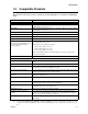
Appendix A Compatible Devices A.1 Two-Wire Smoke Detectors The table below lists two-wire smoke detectors that are compatible with the IntelliKnight fire control panel. The table is organized by manufacturer. The columns show the number of detectors per loop that can be used. Table A-1: Compatible Two-Wire Smoke Detectors Manufacturer Compatibility ID Model Name or Number (Base model name or number in parentheses.
Compatible Devices A.3 Notification Appliances For proper operation, you must use polarized devices with a Model 7628 4.7k ohm EOL resistor on each loop. All supervised notification applicances used with the 5820 must be polarized. The chart below lists notification appliances compatible with the 5395.
Compatible Devices Manufacturer Model Type System Sensor SS2415ADA System Sensor SS2475ADA Strobe System Sensor PS2415ADA Mini-Horn/Strobe System Sensor PS241575ADA Mini-Horn/Strobe System Sensor PS24110ADA Mini-Horn/Strobe System Sensor PS2475ADA Mini-Horn/Strobe Wheelock 46T-G4-24-R Bell Wheelock 46T-G6-24-R Bell Wheelock 46T-G10-24-R Bell Wheelock 46T-G6-24-WS-24-HF-R Strobe/Bell Wheelock 46T-G10-24-WS-24-HF-R Strobe/Bell Wheelock 46T-G6-24-WH-24-HF-R Strobe/Bell Whe
Compatible Devices Manufacturer Model Type Wheelock LSM-24-VFR Remote Strobe Wheelock LS1M-24-VFR Remote Strobe Wheelock LS3M-24-VFR Remote Strobe Wheelock LSPM-24-VFR Remote Strobe Wheelock MS-24-VFR Remote Strobe Wheelock MS1-24-VFR Remote Strobe Wheelock MS3-24-VFR Remote Strobe Wheelock MSP-24-HFR Remote Strobe Wheelock MB-G6-24-R Motor Bell Wheelock MB-G10-24-R Motor Bell Wheelock MBS-G6-24-W-HF-R Motor Bell with Strobe Wheelock MBS-G10-24-W-HF-R Motor Bell with St
Appendix B Word and Special Characters Lists This section contains tables of programmable words or special characters that may be used for device, module, and zone names or phone numbers. B.1 Name Library The IntelliKnight 5820 has a built-in library (or list) of 120 9-character words that are available for you to select for naming points, zones, and groups. You can add up to 136 of your own 9-character words to the library which will then be available to select (see Table B-2).
Silent Knight Fire Product Warranty and Return Policy General Terms and Conditions • All new fire products manufactured by Silent Knight after September 1, 1997 have a limited warranty period of 18 months from the date of manufacture against defects in materials and workmanship. See limited warranty statement for details. • This limited warranty does not apply to those products that are damaged due to misuse, abuse, negligence, or have been modified in any manner whatsoever.