
Specifications


151068 6-1
Section 6
System Configuration
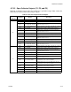
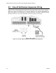
To configure the SK-4224 system set the DIP switch that controls the option you want to
select. The following chart shows how to program the DIP switches that control system, zone,
and notification appliance operation. Refer to Figure 3-1 for location of the DIP switches.
Important!
When you change a DIP switch, be sure to power down the panel. DIP switch changes will be
recognized on power up only.
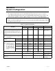
Table 6-1: System Configuration
To Enable
DIP Switch 1 DIP Switch 2
For Zone 1 For Zone 2 For Zone 3 For Zone 4 DIP Position
Enhanced mode (DIP switch ON). Use when both pull
stations and detectors will be used in the same zone.
Normal mode (DIP switch OFF). Use when 4-wire
smoke detectors and smoke verification are used in the
same zone.
SW1 SW6 SW1 SW6 ON = Enhanced
OFF = Normal
Alarm verification
Note: Do not use with smoke detectors that have veri-
fication built-in.
SW 2 SW 7 SW 2 SW 7 ON = Verification zone
OFF = No verification
Zone Type
Fire alarm SW 3 SW8 SW 3 SW8 OFF
Supervisory SW 3 SW8 SW 3 SW8 ON
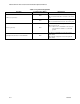
Alarm delay options
Note: Alarm delay options is to
be used with water flow
devices only. If the device
has a built-in delay time
the total delay time (de-
vice delay + programmed
delay) can not exceed 120
seconds.
No delay SW4
SW5
SW9
SW10
SW4
SW5
SW9
SW10
OFF
OFF
30 second delay SW4
SW5
SW9
SW10
SW4
SW5
SW9
SW10
ON
OFF
60 second delay SW4
SW5
SW9
SW10
SW4
SW5
SW9
SW10
OFF
ON
90 second delay SW4
SW5
SW9
SW10
SW4
SW5
SW9
SW10
ON
ON
To Enable For NAC 1 (DIP 3) For NAC 2 (DIP 3) DIP Position
Silencing
SW 1 SW 3 ON = Can be silenced
OFF = No silence
ANSI pattern
SW 2 SW 4 ON = ANSI
Off = Steady