
Specifications
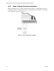

Model SK-4224 Fire Alarm Control Panel Installation/Operation Manual
4-12 151068
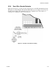
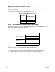
Setting the SK-2866’s address
The range of valid addresses is 0-3. Each device requires a unique address. Set the DIP
switches as shown in Table 4-3. See also Figure 4-11.
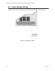
Mounting the SK-2866
The SK-2866 mounts into a standard standard 3-gang electrical box.
Follow these steps to mount the SK-2866:
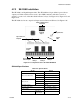
1. Make sure that the SK-2866 is properly wired to the control panel. See Figure 4-11.
2. Slide the printed annunciator label into place on the SK-2866. The label fits in between the
LEDs and the clear plastic plate.
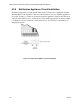
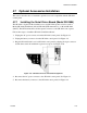
3. Place the SK-2866 into the standard 3-gang electrical box. See Figure 4-12.
Figure 4-12 Mounting the SK-2866
4. Place the cover plate over the top of the SK-2866 and align the holes. See Figure 4-12.
5. Insert the four cover plate screws into the four screw holes on the 3-gang electrical box.
6. Screw the four cover plate screws into the cover plate until the cover plate fits firmly
against the SK-2866 and the electrical box. Do not over tighten.
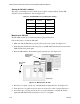
Table 4-3: SK-2866 Addresses Per DIP Switch Setting
DIP Switch Position
Equivalent
Address
Both Open (off) 0
One Closed (on) 1
Two Closed (on) 2
Both Closed (on) 3
Cover Plate
Screw
Cover Plate
Annunciator
Label In
Slide Printed
3-gang
SK-2866
electrical box