
Specifications


Model SK-4224 Fire Alarm Control Panel Installation/Operation Manual
3-8 151068
3.9 Calculating Current Draw and Standby Battery
This section is for helping you determine the current draw and standby battery needs for your
installation.
3.9.1 Worksheet Requirements
The following steps must be taken when determining SK-4224 current draw and standby
battery requirements.
Filling in the Current Draw Worksheet, Table 3-6 (Section 3.9.3)
1. For the SK-4224, the worst case current draw is listed for the panel and is recorded in the
table at Line A.
2. Add up the current draw for all smoke detectors and record in Line B.
3. Add up all notification appliance loads and record in Line C.
4. Any additional devices should be recorded at Line D.
5. Make sure that the alarm current without the panel (Lines B-D) does not exceed 2.5 A.
The total alarm current (including the panel, Lines A-D) should not exceed 2.75 A.
6. Complete the remaining instructions in Table 3-6 for determining battery size require-
ments.
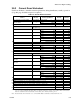
3.9.2 Maximum Battery Standby Load
Table 3-5 shows the maximum battery standby load for the SK-4224 based on 24 and 60 hours
of standby. The standby load calculations of line G in the Current Draw Calculation
Worksheet (Table 3-6) must be less than the number shown in Table 3-5 for the battery size
used and standby hours required.
Note: Batteries greater than 7 AH must be installed in a Silent Knight AB-33 or any enclosure UL listed for Fire
Protective Signaling.
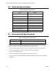
Table 3-5: Maximum Battery Standby Load
Rechargeable Battery Size
Max. Load for 24 hrs.
Standby, 5 mins. Alarm
Max. Load for 60 hrs.
Standby, 5 mins. Alarm
7 AH 270 mA 110 mA
12 AH 425 mA 170 mA