SK-4224 Fire Control Panel Installation and Operation Manual Part Number 151068D, 02/02
Content Section 1 Overview 1.1 1.2 ...................................................................................................................................................... 1-1 SK-4224 Description ................................................................................................................................ 1-1 How to Contact Silent Knight ..................................................................................................................
Model SK-4224 Fire Alarm Control Panel Installation/Operation Manual 4.6 4.7 Door Release Wiring ................................................................................................................................ 4-8 Optional Accessories Installation ............................................................................................................. 4-9 4.7.1 Installing the Serial Driver Board (Model SK-2884) .......................................................................
Section 1 Overview 1.1 SK-4224 Description The Model SK-4224 is a four zone, 24-volt fire alarm control panel having the following features: • Zone inputs can be configured as: Four Class B zones Or Two Class A zones • 2.5 amp power supply • Two notification appliance circuits rated at 2.5 amp total. • Dedicated alarm and trouble relays • Auxiliary power output (.5 amp max.) for powering special applications, such as door holders.
Model SK-4224 Fire Alarm Control Panel Installation/Operation Manual 1-2 151068
Section 2 Agency Requirements 2.1 FCC Warning This device has been verified to comply with FCC Rules Part 15. Operation is subject to the two following conditions: (1) This device may not cause radio interference, and (2) This device must accept any interference received, including interference that may cause undesired operation. 2.2 Underwriters Laboratories (UL) The SK-4224 is UL listed as a control unit for use in NFPA 72 systems.
Model SK-4224 Fire Alarm Control Panel Installation/Operation Manual 2-2 151068
Section 3 Before You Begin Installing 3.
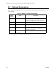
Model SK-4224 Fire Alarm Control Panel Installation/Operation Manual 3.2 Optional Accessories Table 3-2 is a list of optional accessories that can be used with the Model SK-4224 Fire Alarm Control Panel. Table 3-2: Option Accessories for the SK-4224 Model Number * 3-2 Name Description SK-2884 Serial Driver Board Used to interface all SK-4224 expansion devices to the SK4224 panel.
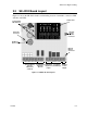
Before You Begin Installing 3.3 SK-4224 Board Layout Figure 3-1 shows the SK-4224 circuit board including location of terminals, connectors, DIP switches, and LEDs.
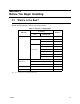
Model SK-4224 Fire Alarm Control Panel Installation/Operation Manual 3.4 Electrical Specifications Table 3-3: Electrical Specifications Circuit Rating Primary AC *120 Vrms at 60 Hz, or 230 Vrms at 50 Hz @ 1.5 amps Total External DC Load 2.5A @ 24 VDC +24V Auxiliary Power 19.8 V to 28.0 V, 0.5 A max. Trouble & Alarm Relays 2.5 A @ 30 VDC resistive Notification Appliance Power 19.8 V to 28.0 V, 2.5 A max. Smoke Detector Power 19.8 V to 28.0 V, 1.0 A max. Battery Charging Voltage 27.0 - 27.
Before You Begin Installing 3.6 Mounting the SK-4224 Read the environmental specifications in Section 3.5 before mounting the cabinet. The panel should be accessible to main drop wiring runs. It should be mounted as close to the center of the building as possible and located within a secured area, but should be accessible for testing and service. End-users responsible for maintaining the panel should be able to hear alarms and troubles.
Model SK-4224 Fire Alarm Control Panel Installation/Operation Manual 3.7 Assembly The components listed in Table 3-1 are all packed with in the cabinet and require some assembly. Follow these steps to assemble the components within the cabinet: 1. Remove keys from the envelope taped to the top of the cabinet. 2. Unlock the cabinet door. 3. Remove the packing material and the SK-4224 components. 4. Snap the bezel into the opening in the front of the cabinet. See Figure 3-3.
Before You Begin Installing 3.8 Wiring Specifications Induced noise (transfer of electrical energy from one wire to another) can cause false alarms or interfere with control panel operation in other ways. To avoid induced noise, follow these guidelines: • Isolate input wiring from high current output and power wiring. Do not pull one multiconductor cable for the entire panel. Instead, separate the wiring as follows: Important! Do not run 120 VAC line voltage in fire alarm raceways.
Model SK-4224 Fire Alarm Control Panel Installation/Operation Manual 3.9 Calculating Current Draw and Standby Battery This section is for helping you determine the current draw and standby battery needs for your installation. 3.9.1 Worksheet Requirements The following steps must be taken when determining SK-4224 current draw and standby battery requirements. Filling in the Current Draw Worksheet, Table 3-6 (Section 3.9.3) 1.
Before You Begin Installing 3.9.3 Current Draw Worksheet Use this worksheet to determine current requirements during alarm/battery standby operation. (Copy this page if additional space is required.
Model SK-4224 Fire Alarm Control Panel Installation/Operation Manual 3-10 151068
Section 4 Hardware Installation 4.1 AC Power At installation, connect the transformer AC inputs to the AC power source as shown in Figure 4-1. It may be necessary for a professional electrician to make this connection. The AC inputs are rated as 120 VAC, 60 Hz (for transformer P/N 115061) or 230 VAC, 50 Hz (for transformer P/N 115031). See Table 3-1 for more information.
Model SK-4224 Fire Alarm Control Panel Installation/Operation Manual 4.2 Battery Connection The SK-4224 battery charge capacity is 7.0 AH. Use two Model 12 VDC batteries of the same AH rating. Determine the correct AH rating as per your current load calculation (see Table 36). Wire batteries in series to produce a 24-volt equivalent. Do not parallel batteries to increase the AH rating. Note: The SK-4224 cabinet supports two 7.0 AH batteries.
Hardware Installation 4.3 4.3.1 Initiating Circuit Installation Contact Wiring Wire normally open contacts as shown in Figure 4-3. This is the type of wiring that would typically be used for manual stations, heat detectors and other normally open devices. Figure 4-3 N.O. Contact Wiring 4.3.2 Two-Wire Smoke Detector Wiring Figure 4-4 shows how to connect two-wire smoke detectors to the SK-4224 initiating circuits. The figure uses Silent Knight’s SLK-24F with HSB-224 base as an example.
Model SK-4224 Fire Alarm Control Panel Installation/Operation Manual 4.3.3 Class A Smoke Detector Installation Figure 4-5 illustrates how to connect a UL listed smoke detector to the SK-4224 in a Class A configuration. Refer to the Appendix for a list of compatible devices. Information on selecting zone configuration options is in Section 6.
Hardware Installation 4.3.4 Four-Wire Smoke Detector Figure 4-6 shows how to connect four-wire smoke detectors to the SK-4224 initiating circuits. The figure uses Silent Knight’s SLK-24F with HSC-4R base as an example. You can use any UL listed device. Refer to the Appendix for a list of compatible devices. Information on selecting zone configuration options is in Section 6.
Model SK-4224 Fire Alarm Control Panel Installation/Operation Manual 4.3.5 Notification Appliance Circuit Installation Notification appliances used with the SK-4224 must be UL listed for compatibility with the SK-4224. Refer to the Appendix at the end of this manual for a list of compatible appliances. For proper operation, you must use polarized notification appliances with a model 7628 4.7k ohm end-of-line (EOL) resistor on each circuit. Select ANSI output pattern, if desired.
Hardware Installation 4.3.6 Class A Notification Appliance Circuit Installation For proper operation, you must use polarized notification appliances. Select ANSI output pattern, if desired. Output is configured as steady (continuous sound) at the factory. See Section 6 for information on changing the pattern. Figure 4-8 Class A Notification Circuit 4.4 Alarm and Trouble Relays The SK-4224 has built-in relays for alarm and trouble. The alarm relay is energized during any alarm condition.
Model SK-4224 Fire Alarm Control Panel Installation/Operation Manual 4.6 Door Release Wiring Figure 4-9 shows how to configure a door release using an ESL DH series door holder.
Hardware Installation 4.7 Optional Accessories Installation This section describes how to install the optional accessories compatible with the SK-4224 control panel. 4.7.1 Installing the Serial Driver Board (Model SK-2884) The SK-2884 is required if the installation uses any SK-4224 expansion devices such as Model SK-2880 (I/O Module), Model SK-2866 (LED Annunciator), or Model SK-2104 (DACT). The SK-2884 interfaces all the expansion devices to the SK-4224 control panel.
Model SK-4224 Fire Alarm Control Panel Installation/Operation Manual Wiring the SK-2884 to an Expansion Device The SK-2884 uses a three wire connection to all of the SK-4224 compatible expansion devices (see Table 3-2). Connect all the expansion devices to the SK-2884 as follows: Table 4-1: SK-2884 Wiring Connections 4.7.
Hardware Installation 3. Terminate the wiring as shown in Figure 4-11. See also Table 4-2.
Model SK-4224 Fire Alarm Control Panel Installation/Operation Manual Setting the SK-2866’s address The range of valid addresses is 0-3. Each device requires a unique address. Set the DIP switches as shown in Table 4-3. See also Figure 4-11. Table 4-3: SK-2866 Addresses Per DIP Switch Setting DIP Switch Position Equivalent Address Both Open (off) 0 One Closed (on) 1 Two Closed (on) 2 Both Closed (on) 3 Mounting the SK-2866 The SK-2866 mounts into a standard standard 3-gang electrical box.
Hardware Installation 4.7.3 SK-2880 Installation The SK-2880 is an Input/Output module. The SK-2880 has 34 pre-defined open collector outputs (see Table 4-6) that can be used to drive LEDs, interface with other controls or systems, or control one of the three built-in Form C relays. See Figure 4-13, Figure 4-15 and Figure 4-16. The SK-2880 also has two supervised inputs used for Reset and Silence. See Figure 4-16.
Model SK-4224 Fire Alarm Control Panel Installation/Operation Manual 4.7.3.1 Connecting the SK-2880 to the SK-2884 The control panel communicates to the I/O module through the Serial Interface Board (see also Section 4.7.1). Figure 4-14 illustrates how to properly wire the I/O module to the Serial Interface Board. Supervised Power Limited SK-2880 SK-2884 Figure 4-14 I/O Module Wiring 4.7.3.2 Setting the SK-2880 Address The range of valid addresses is 0-3.
Hardware Installation 4.7.3.3 Open Collector Outputs (P1, P2, and P3) Each pin on the Pin Connectors (P1, P2, and P3) have a predefined output. Table 4-6 lists the Pin Connectors and describes what each pin outputs. Table 4-6: Pin-outs for Open Collector Outputs Pin Connector P1 P2 151068 Pin Number Output Description Pin 1 Zone 1 Alarm/Supervisory Outputs when there is an alarm or supervisory on Zone 1. Pin 2 Zone 1 Trouble Outputs when a trouble condition exists on Zone 1.
Model SK-4224 Fire Alarm Control Panel Installation/Operation Manual Table 4-6: Pin-outs for Open Collector Outputs Pin Connector Pin Number Output Description Pin 1 NAC 1 Trouble Outputs when a trouble condition exists on NAC 1. Pin 2 NAC 2 Trouble Outputs when a trouble condition exists on NAC 2. Pin 3 NAC 3 Trouble Outputs when a trouble condition exists on NAC 3.
Hardware Installation 4.7.3.4 SK-2880 Input Switches and Relay Wiring This section describes the components of terminal strip 2 (see Figure 4-13) on the SK-2880. Terminal strip 2 provides two input switches (Reset & Silence) and three Form C relays. Figure 4-16 illustrates how to configure the inputs switches and the Form C Relays. Any Open Collector Output UL Listed EOL 4.7 KΩ Model 4.7 KΩ 7628 Supervised Power Limited Power Limited Dry Contact outputs must be connected to a power limited source.
Model SK-4224 Fire Alarm Control Panel Installation/Operation Manual 4.7.3.5 Mounting the SK-2880 The I/O module must be mounted by itself inside a UL Listed (for Fire Protective Signal) accessory cabinet. Follow these steps to mount the SK-2880: 1. Remove the SK-2880’s cover. A small screw driver can be used. 2. Remove the SK-2880 circuit board from the base by pushing outward on the base retaining tabs and lift the circuit board out. See Figure 4-17.
Section 5 Notification Expansion Mode The SK-4224 can be used to expand the power capabilities of an existing system’s notification appliance circuits. The SK-4224 does this by connecting the notification appliance circuits of an existing or host fire alarm control panel to the FACP input of the SK-4224, which can trigger the SK-4224 circuits when the host panel goes into alarm.
Model SK-4224 Fire Alarm Control Panel Installation/Operation Manual 5.2 Class B Notification Expansion Wiring Figure 5-2 shows Class B supervised wiring from a host fire alarm control panel to the SK4224 control panel. Use an EOL resistor as shown in Figure 5-2 to supervise the FACP input. The host fire alarm control panel may use an EOL with a value other than 4.7 KΩ, used by the SK-4224. In this case, use an UL listed EOL for the host panel you are using.
Section 6 System Configuration To configure the SK-4224 system set the DIP switch that controls the option you want to select. The following chart shows how to program the DIP switches that control system, zone, and notification appliance operation. Refer to Figure 3-1 for location of the DIP switches. Important! When you change a DIP switch, be sure to power down the panel. DIP switch changes will be recognized on power up only.
Model SK-4224 Fire Control Panel Installation/Operation Manual Table 6-1: System Configuration To Enable For Entire Panel (DIP 3) DIP Position ON = Serial Annunciator connected to the control panel. SW5 Serial Accessory Devices SW6 OFF = No Serial Annunciator connected to the control panel. ON = Serial DACT connected to the control panel OFF = No Serial DACT connected to the control panel. ON = 6 hour delay on AC loss report. OFF = No delay on AC.
Section 7 System Operation The annunciator on the SK-4224 board is used for all system operation. It contains the switches for enabling silencing, resetting, and so on. The LEDs that indicate system status are also located on the annunciator. Figure 7-1 On-Board Annunciator 7.1 Meaning of LEDs The chart below explains the meaning of LEDs on the system board.
Model SK-4224 Fire Alarm Control Panel Installation/Operation Manual Table 7-1: Meaning of LEDs LED (Color) GND FAULT (yellow) Function ON = Ground fault condition exists and was acknowledged OFF = No fault Comments If flashing, press the ACK button to acknowledge the condition. FLASHING = A ground fault condition detected LOW BATTERY (yellow) ON = Battery low condition that has been acknowledged OFF = Good battery condition If flashing, press the ACK button to acknowledge the condition.
System Operation 7.2 Operation Keys (Switches) All system operations are performed from the on-board keys (switches) as described in the chart below. Table 7-2: Operations and Instructions Operation Keystrokes Disable notification appliance circuit. Press the appropriate [NAC DISABLE] key. The NAC circuit will be disabled and the corresponding TROUBLE LED will Double Flash. This function is not available during an alarm condition. To re-enable the circuit, press [NAC DISABLE] again.
Model SK-4224 Fire Alarm Control Panel Installation/Operation Manual 7-4 151068
Appendix A Compatible Devices This section of the manual lists devices (smoke detectors and notification appliances) that are compatible with the SK-4224. Contact Silent Knight if you have a question about whether a device not listed here is compatible. A.1 Smoke Detectors This section of the manual contains information about smoke detectors that are compatible with the SK-4224. SK-4224 Identifier Voltage Range 24F for Class B zones 16.2-27.
Model SK-4224 Fire Alarm Control Panel Installation/Operation Manual A.1.2 Two-Wire Smoke Detectors The table below lists two-wire smoke detectors that are compatible with the SK-4224. The columns show the number of detectors per circuit that can be used. The two-wire compatibility identifier is 24F. Note: The check mark indicates that this device can be used in enhanced mode.
Compatible Devices Table A-1: Compatible Two-Wire Smoke Detectors Manufacturer Enhance Mode Compatible Compatibility ID Model Name or Number (Base model name or number in parentheses.
Model SK-4224 Fire Alarm Control Panel Installation/Operation Manual Table A-1: Compatible Two-Wire Smoke Detectors Manufacturer Enhance Mode Compatible Compatibility ID Model Name or Number (Base model name or number in parentheses.) # per Circuit Head Base 2300 A N/A 20 / loop 2300TB A N/A 20 / loop 2400 A N/A 20 / loop 2400 (DH400) A N/A 20 / loop 2400AIT A N/A 20 / loop 2400AT A N/A 20 / loop 2400TH A N/A 20 / loop System Sensor 2451 (B401B) A N/A 20 / loop (Cont.
Compatible Devices Table A-1: Compatible Two-Wire Smoke Detectors Manufacturer Enhance Mode Compatible Model Name or Number (Base model name or number in parentheses.
Model SK-4224 Fire Alarm Control Panel Installation/Operation Manual Four-Wire Smoke Detectors Table A-2: Compatible Four-Wire Smoke Detectors Manufacturer A-6 Model Silent Knight SD-P24F with SD-B4@ base Detection Systems DS200/DS200HD MB200 ESL 445 Series 449 Series Gentex 624 824 2040-24 Power Supervision Unit System Sensor 1851B 2851/2851BTH DH200ADCD 151068
Compatible Devices A.2 Notification Appliances The chart below lists notification appliances compatible with the SK-4224. Note: Units that operate at 12 or 24 VDC must be selected for 24 VDC operation.
Model SK-4224 Fire Alarm Control Panel Installation/Operation Manual Table A-3: Compatible Notification Appliances Manufacturer Faraday (Cont.
Compatible Devices Table A-3: Compatible Notification Appliances Manufacturer FCI (Cont.) Federal Signal Gentex 151068 Model Type P2475K-FC Horn/Strobe P24110-FC Horn/Strobe P24110W-FC Horn/Strobe P24110K-FC Horn/Strobe S2415-FC Strobe S241575-FC Strobe S241575W-FC Strobe S241575K-FC Strobe S2430-FC Strobe S2430W-FC Strobe S2430K-FC Strobe S2475-FC Strobe S2475W-FC Strobe S2475K-FC Strobe S24110-FC Strobe S24110W-FC Strobe S24110K-FC Strobe MDL-FC Sync.
Model SK-4224 Fire Alarm Control Panel Installation/Operation Manual Table A-3: Compatible Notification Appliances Manufacturer System Sensor System Sensor (Cont.
Compatible Devices Table A-3: Compatible Notification Appliances Manufacturer Wheelock 151068 Model Type 46T-G4-24-R Bell 46T-G6-24-R Bell 46T-G10-24-R Bell 46T-G6-24-WS-24-HF-R Strobe/Bell 46T-G10-24-WS-24-HF-R Strobe/Bell 46T-G6-24-WH-24-HF-R Strobe/Bell 46T-G10-24-WH-24-HF-R Strobe/Bell 7001T-12\24-W-FR Strobe Horn 7002T-12\24-W-FR Strobe Horn AES-DL1-R Multitone Horn AES-EL1-R Multitone Horn AES-DL1-WS-24-VF-R Multitone Horn AES-EL1-WS-24-VF-R Multitone Horn AES-DL1-WH-24
Model SK-4224 Fire Alarm Control Panel Installation/Operation Manual Table A-3: Compatible Notification Appliances Manufacturer Wheelock (Cont.
Compatible Devices Table A-3: Compatible Notification Appliances Manufacturer Wheelock (Cont.
Model SK-4224 Fire Alarm Control Panel Installation/Operation Manual Table A-3: Compatible Notification Appliances Manufacturer Wheelock (C0nt.
Compatible Devices Table A-3: Compatible Notification Appliances Manufacturer Wheelock (Cont.
Model SK-4224 Fire Alarm Control Panel Installation/Operation Manual Table A-3: Compatible Notification Appliances Manufacturer Wheelock (Cont.
SK-4224 Basic Operating Instructions P/N 151066 These instructions must be framed and displayed next to the SK-4224 panel in accordance with NFPA 72 fire code for Local Fire Alarm System. LED (Color) Comments ON = Good AC OFF = Low AC trouble condition and it was acknowledged FLASHING = Unacknowledged AC Low trouble condition GENERAL TROUBLE (yellow) ON = System trouble OFF = System OK FLASHING = At least one serial device is in trouble DOUBLE FLASHING = Two types of serial devices are in trouble.
Cut Along the Dotted Line
Silent Knight Fire Product Warranty and Return Policy General Terms and Conditions • All new fire products manufactured by Silent Knight have a limited warranty period of 18 months from the date of manufacture against defects in materials and workmanship. See limited warranty statement for details. • This limited warranty does not apply to those products that are damaged due to misuse, abuse, negligence, exposer to adverse environmental conditions, or have been modified in any manner whatsoever.
• A new or refurbished board will be shipped to the customer. The customer will initially be billed for the replacement board but a credit will be issued after the repairable board is received at Silent Knight. All returned products must comply with the guidelines described under “General Terms and Conditions”. • The defective board must be returned within 30 days of shipment of replacement board for customer to receive credit.
7550 Meridian Circle Maple Grove, MN 55369-4927 763-493-6455 1-800-328-0103 Fax: 763-493-6475 © 2002 Silent Knight Part Number 151068D, 02/02