
Technical data


Regulación AC Brushless digital - Ref.0707 MCSi-5/84
GENERAL INDEX
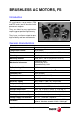
BRUSHLESS AC MOTORS, FS ..................................................................................7
Introduction ..................................................................................................................7
General characteristics ................................................................................................7
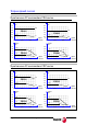
Torque-speed curves ...................................................................................................9
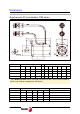
Dimensions ................................................................................................................10
Base power connectors and encoder output..............................................................12
Brake characteristics..................................................................................................13
Sales reference..........................................................................................................14
A.C. SERVODRIVE....................................................................................................15
Introduction ................................................................................................................15
General characteristics ..............................................................................................15
Dimensions ................................................................................................................15
Technical data............................................................................................................16
Connectors.................................................................................................................17
Indicators (LED's).......................................................................................................21
Push-buttons and switches ........................................................................................21
Programming module.................................................................................................22
Front view of the module............................................................................................23
Top view of the module ..............................................................................................24
Pinout of the connectors ............................................................................................24
Sales reference..........................................................................................................26
INSTALLATION..........................................................................................................27
General considerations ..............................................................................................27
Electrical connections ................................................................................................28
Diagram of the electrical cabinet................................................................................38
Initialization and adjustment.......................................................................................41
PARAMETERS, VARIABLES AND COMMANDS .....................................................46
B group. Non-programmable inputs - outputs ............................................................48
C group. Current ........................................................................................................48
D group. Diagnosis.....................................................................................................52
E group. Encoder simulator........................................................................................54
G group. General .......................................................................................................54
H group. Hardware.....................................................................................................56
I group. Inputs ............................................................................................................57
K group. Monitoring....................................................................................................59
M group. Motor...........................................................................................................60
O group. Analog and digital outputs...........................................................................61
Q group. Communication ...........................................................................................64
S group. Speed ..........................................................................................................66
T group. Torque and power........................................................................................71
W group. Internal generator .......................................................................................72
ERROR MESSAGES .................................................................................................74