
Technical data


MCSi-40/84 Digital Brushless AC servo drive system - Ref.0707
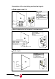
The following figure shows the diagram of the safe disable (SD) of an MCS Innova and
as an example of application, a diagram to control the access to areas with moving
elements:
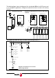
The diagram to control the access to areas with moving elements is:
DRIVE 1
Work Zone 1 Work Zone 2
S1
MCS
Innova
DRIVE 2 DRIVE 3 DRIVE 4 DRIVE 5
MCS
Innova
MCS
Innova
MCS
Innova
MCS
Innova
Mains
L2
L1
R
S
T
S2
Inductance
Drive Enable
Pin 41 (X3)
Pin 42 (X3)
Drive Enable
Pin 41 (X3)
Pin 42 (X3)
Drive Enable
Pin 41 (X3)
Pin 42 (X3)
Drive Enable
Pin 41 (X3)
Pin 42 (X3)
Drive Enable
Pin 41 (X3)
Pin 42 (X3)
{
M
Mains
CONTROL
MCS
Innova
L2 L1
RST
Pins 41 & 42
(X3)
Drive Enable
Pin 13 (X3)
Safety Relay
MCS
Innova
Inductance
Integrated-safety relay
Diagram to control the access to areas with moving
elements
S1
K1
Pins 41 & 42 (X3)
Drive 1
+24 V DC
Emergency button
Locking up
drives 1 & 2
Drive Enable 1
Drive Enable 2
Drive Enable 3
Drive Enable 4
Drive Enable 5
Cycle Stop
Cycle Start
System OK.
K1
Pins 41 & 42 (X3)
Drive 2
Pins 41 & 42 (X3)
Drive 3
Pins 41 & 42 (X3)
Drive 4
Pins 41 & 42 (X3)
Drive 5
S2
Locking up
drives 3, 4 & 5
Diagram to control the access to areas
with moving elements