
Technical data


MCSi-30/84 Digital Brushless AC servo drive system - Ref.0707
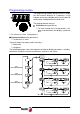
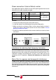
Power connection. External Ballast resistor
If the application requires a Ballast resistor with a power greater than the one
indicated in this table according to model:
therefore:
Remove the cable joining the terminals Ri and L+.
Install the external resistor between the terminals Re and L+.
Make sure that the resistance (Ohms) of the external ballast resistor is
exactly the same as that of the internal resistor of that module. See the
general characteristics table.
Use KV41 to indicate to the drive that an external ballast resistor has been
connected.
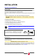
Inductance for reducing high frequency harmonics
It is recommended to connect an inductance at the input of one of the power
phases L1 or L2 of the drive (connector X4) to reduce high frequency harmonics
coming from mains with a value of 5 mH and and rms current of 6 Arms. This
inductance reduces the disturbances in mains, but it does not ensure
compliance with CE regulations. Connect the inductance as shown in the
figure.
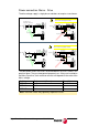
Mains filter to suppress electromagnetic interference
In order for the Fagor DDS servo drive system to meet the European Directive
on Electromagnetic Compatibility 92/31/CE, the mains filter FAGOR FEHV-
XXX must be inserted (see the table in the next section “connection”) at the input
of the MCSi (power phases L1 and L2 of connector X4) against electromagnetic
interference.
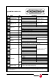
Model
Internal
resistor Ri
Maximum power
that may be
External
resistor
MCSi 07L ----- ----- -----
Max. value 65 Ω
Min. value 45 Ω
MCSi 11L ----- ----- -----
MCSi 15L 45 Ω 60 W 15 W
L+
Re
Ri
2.5 mm
2
External Ballast
L+
Re
Ri
X9
Internal
Ballast
X9
Re Ri L+
X9
X9. Connector on top of the drive module.