
Technical data


Digital Brushless AC servo drive system - Ref.0707 MCSi-25/84
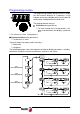
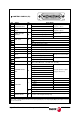
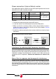
CONTROL SIGNALS (X3)
Pin Signal I/O Description
2
ANALOG VELOCITY
COMMAND INPUT
I
Input +
Range ± 10 V,
impedance 56 kΩ
1
Input -
18
PROG. ANALOG
INPUT
I
Input +
Range ± 10 V,
impedance 56 kΩ
17
Input -
31
PROG. ANALOG
OUTPUT
O
Programmable analog output 1
Range ± 10 V
32
Programmable analog output 2
16
GND
34
AUX. ±12 V
O
+12 V (20 mA max) output
33
-12 V (20 mA max) output
19
GND
43
AUX 24 V DC
O
+24 V DC (50 mA max) output
44
GND AUX 24 V DC
13
DRIVE ENABLE I DRIVE ENABLE input (range from 0 to 24V DC)
15
SPEED ENABLE I SPEED ENABLE input (range from 0 to 24V DC)
14
COMMON DRIVE --- Common to inputs DRIVE ENABLE and SPEED ENABLE
11
PROG. DIGIT.
INPUT
I
Programmable digital input +
Range from 0 to 24 V DC
12
Common of the digital input -
27
PROG. DIGIT.
OUTPUT
O
Programmable digital output (collector)
100 mA max, 50 V DC
28
Programmable digital output (emitter)
29
DRIVE OK O
Open contact of the DRIVE OK signal
(0,6 A - 125 V DC, 0,5 A - 110 V DC, 2 A - 30 V DC)
30
22
ENCODER SIMUL.
OUT
O
A + signal
Encoder simulator outputs.
(range from 0 to 5 V)
7
A - signal
24
B + signal
8
B - signal
37
Z + signal
38
Z - signal
23
GND
6
AUXILIARY
I
A + signal
5
A - signal
21
B + signal
36
B - signal
20
Z + signal
35
Z - signal
4
O
+ 5 V. Supply for the direct feedback device (0.5 A max)
3
Supply GND for the direct feedback device
41
SAFETY RELAY O
Second contact (NC
normally closed) used as external acknowledgment of
the status of the integrated safety relay.
42
Pins 9, 10, 25, 26, 39 and 40 are NC (not connected).
The < I/O > column indicates whether it is an input signal (Input) or an output signal (Output) through the relevant
pin at connector X3.
1
16
31
44
30
15