
Technical data


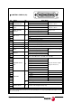


Digital Brushless AC servo drive system - Ref.0707 MCSi-23/84
There are also a set of variables and certain commands of special characteristics whose
meaning and sequences to follow are described in section “initialization and setup” in
this manual.
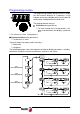
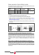
Front view of the module
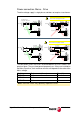
Interpretation of the symbols used in some diagrams of this manual.
Blinking status of the two rightmost digits of the display.
Blinking status of the two leftmost digits of the display.
Long push on the programming module.
Short push on the programming module.
Rotary decoder on the programming module.
L
C
COMMUNICATIONS
FEEDBACK INPUT
+5V
CROWBAR
VBUS OK
RESET
PUSH TO CONFIRM
JOG
CONTROL SIGNALS
CONTROL POWER INPUT
L1
220V
L2
MOTOR POWER INPUTS
L1
220V
L2
W
V
U
ON OFF
Four 7-segments displays
Programming module
Sign indicating display
Input terminals for the voltage supply of the
control circuits from mains. (single-phase 220
V AC).
Mains input terminals for the module voltage
supply (single phase 220 V AC) and voltage
output terminal to the motor (three-phase 220
V AC).
Control signals. Analog inputs and outputs,
encoder simulator, direct feedback, enables,
digital inputs and outputs, drive ok, integrated
safety relay, chassis.
Encoder signal input.
Line terminating resistor on/off selecting
switch.
Module connection via RS485 serial line.
LED's indicating that there is voltage at the
bus, that the crowbar is activated (VBUS OK/
CROWBAR (ON) and that there are internal
+5V.
Reset button