
Technical data


Digital Brushless AC servo drive system - Ref.0707 MCSi-21/84
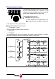
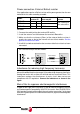
Indicators (LED's)
+5 V: LED located on top of connector X1. When lit, it indicates that the
internal +5 V are being applied.
CROWBAR (ON) / VBUS OK: Two-color (green/red) light indicator located
next to the + 5 V LED. It indicates its status according to the following table:
Push-buttons and switches
RESET: Push-button for resetting the system.
TERMINATING RESISTOR (COMMUNICATIONS): This switch located
next to the connector X1 (front of the module) may be used to connect or
disconnect the line terminating resistor in RS485 communications.
COMMUNICATIONS
+ 5V
CROWBAR
VBUS OK
ON OFF
+ 5V
CROWBAR (ON)
VBUS OK
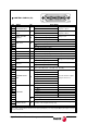
STATUS OF THE LED CROWBAR (ON) / VBUS OK
OFF No voltage at power circuit
ON (RED)
The internal bus voltage is higher than
preset values and the recovery resistor
has been activated
ON (GREEN)
Voltage at power circuit
COMMUNICATIONS
+ 5V
CROWBAR
VBUS OK
ON OFF
SWITCH TERMINAL RESISTOR
(COMMUNICATIONS)
LINE TERMINATING RESISTOR SWITCH POSITION
"ON" POSITION
Resistor connected
"OFF" POSITION
Resistor not connected