
Technical data
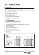


Digital Brushless AC servo drive system - Ref.0707 MCSi-19/84
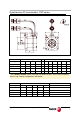
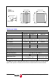
DIRECT FEEDBACK
Auxiliary Feedback Input , pins 5, 6, 36, 21, 35, 20, 4 and 3: Input to connect
a second feedback device with TTL signals. The connector provides an
auxiliary + 5 V DC (0.5 A max) for the feedback device (see pin 4).
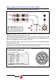
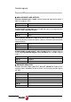
ENABLES
Drive Enable input, pin 13: No current circulates through the motor stator
winding at 0 V DC, thus it no longer supplies torque. It is activated with +24
V DC.
Speed Enable input, pin 15: At 0 V DC, it forces an internal zero velocity
command. It is activated with +24 V DC.
Common to inputs Drive Enable and Speed Enable pin 14: Reference
point for inputs Drive Enable and Speed Enable.
+24 V DC and 0 V DC, pins 43 and 44: Output of the internal 24 V DC
power supply that may be used for the control of inputs Drive Enable and
Speed Enable as well as the programmable digital input. It offers a
maximum current of 50 mA limited internally.
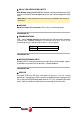
DIGITAL INPUTS AND OUTPUTS
Programmable digital input, pins 11 and 12: Digital input (servo drive at
+24 V DC and 0 V DC) used as input for some integrated functions.
Programmable digital output, pins 27 and 28: Optocoupled open
collector output that reflects the output of some integrated functions.
DRIVE OK
Drive Ok, pins 29 and 30: Relay contact that closes when the internal status
of the drive control is OK.
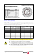
PIN 6 A+
PIN 5 A -
PIN 21 B+
PIN 36 B -
PIN 20 Z+
PIN 35 Z -
PIN 3 GND
PIN 4 + 5 V DC (0.5 A max.)
PIN 13 DRIVE ENABLE
PIN 15 SPEED ENABLE
PIN 14 Pin common to inputs DRIVE ENABLE and SPEED ENABLE
PIN 43 +24 V DC of the auxiliary power supply (max. 50 mA)
PIN 44 GND of the auxiliary 24 V DC power supply
Note that this relay contact must be necessarily included in the electrical
maneuver.