
Technical data
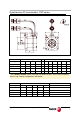
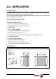
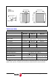


MCSi-18/84 Digital Brushless AC servo drive system - Ref.0707
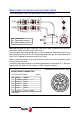
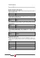
Control signals
Conector X3
ANALOG INPUTS AND OUTPUTS
Velocity command, pins 1 and 2: Velocity command input for the motor. It
admits a range of ± 10 V.
Programmable analog input, pins 17 and 18: Input for analog command
used for some integrated functions.
± 12 V, pins 33, 34 and 19: Output of an internal power supply so the user
can easily generate a command signal. It offers a maximum current of 20 mA
limited internally.
Programmable analog output 1, pins 31 and 16 with a voltage range of
±10 V and programmable output 2, pins 32 and 16 with a voltage range of
± 10 V.
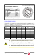
ENCODER SIMULATOR
Encóder Simulator Output , pins 22, 7, 24, 8, 37, 38 and 23: Outputs of the
encoder signals divided by the preset factor, for closing the position loop at
the CNC.
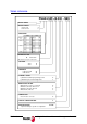
PIN 1 Input -
PIN 2 Input +
PIN 17 Input -
PIN 18 Input +
PIN 34 +12 V
PIN 33 -12 V
PIN 19 GND
PIN 31 Output 1
PIN 32 Output 2
PIN 16 Common
PIN 22 A+
PIN 7 A -
PIN 24 B+
PIN 8 B -
PIN 37 Z+
PIN 38 Z -
PIN 23 GND