
Technical data
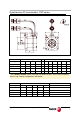
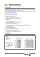


Digital Brushless AC servo drive system - Ref.0707 MCSi-13/84
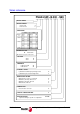
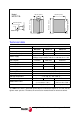
Brake characteristics
FSA and FSP series motors have an optional brake that applies friction to the shaft. Its
purpose is to immobilize or lock vertical axes, not to brake a moving axis. Its main
characteristics depending on the type of brake are:
Brake
Holding
torque
Power
consumption
Supply
voltage
Mass Inertia
Motor type Nm (lbf· In) W (hp) V DC kg (lbf)
kg·cm
2
FSA01 0.318 (2.814) 6.0 (0.008) 24 0.300 (0.66) 0.0085
FSA02 0.637 (5.637) 6.9 (0.009) 24 0.500 (1.10) 0.058
FSA04 1.270 (11.240) 6.9 (0.009) 24 0.500 (1.10) 0.058
FSA08 2.390 (21.153) 7.7 (0.010) 24 0.900 (1.98) 0.058
FSP01 0.318 (2.814) 8.1 (0.010) 24 0.200 (0.44) 0.029
FSP02 0.637 (5.637) 7.6 (0.010) 24 0.500 (1.10) 0.109
FSP04 1.270 (11.240) 7.6 (0.010) 24 0.500 (1.10) 0.109
FSP08 2.390 (21.153) 7.5 (0.010) 24 1.500 (33.1) 0.875
The brake must not be used to stop the axis while it is moving.
The brake must never exceed its maximum turning speed.
A voltage between 22 V and 26 V releases the shaft. Make sure that
no voltage over 26V is applied that prevent the shaft from turning.
When installing the motor, make sure that the brake fully releases
the shaft before making it turn for the first time.
1
2
3
4
5
6
7
8
9
10
11
12
13
14
15
16
17
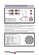
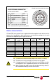
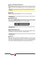
BASE FEEDBACK CONNECTOR
On FSA and FSP motors (200 V)
Note 1. The rest of pins are not connected
SignalPin Color
1
0 V (16 bit absolute) Pink
2
3.6 V (16 bit absolute) Grey
3
+ RS485 Green
4
- RS485 Yellow
8
+ 5 V White
9
0 V Brown
Note 2. Connector housing connected to ground
Viewed from the outside of the motor