FAGOR AUTOMATION S.COOP. Brushless AC servo drives ~ MCS Innova series ~ Ref.
Title Type of documentation Name Reference Software WinDDSSetup Electronic document Headquarters Brushless AC Servo Drives (MCS Innova series) Description, installation and startup of small motors and digital drives. MAN_MCSi_DRIVE SYSTEM (ing.) Ref.0707 Version 01.0x Version 06.1x MAN_MCSi_DRIVE SYSTEM.pdf FAGOR AUTOMATION S. COOP. Bº San Andrés 19, Apdo. 144 20500 ARRASATE- MONDRAGÓN www.fagorautomation.com info@fagorautomation.
WARRANTY INITIAL WARRANTY: All products manufactured or marketed by FAGOR carry a 12-month warranty for the end user. In order to prevent the possibility of having the time period from the time a product leaves our warehouse until the end user actually receives it run against this 12-month warranty, the OEM or distributor must communicate to FAGOR the destination, identification and installation date of the machine by filling out the Warranty Form that comes with each product.
DECLARATION OF CONFORMITY Manufacturer: Fagor Automation, S. Coop. Bº San Andrés 19, C.P. 20500, Mondragón -Guipúzcoa- (SPAIN) We hereby declare, under our responsibility that the product: Fagor AC Brushless Servo Drive System consisting of the following modules and motors: Drive modules: MCS Innova (MCSi) series AC motors: FS. FSA and FSP series.
GENERAL INDEX BRUSHLESS AC MOTORS, FS ..................................................................................7 Introduction ..................................................................................................................7 General characteristics ................................................................................................7 Torque-speed curves ...................................................................................................9 Dimensions .......
WARNINGS ...............................................................................................................79 LIST OF PARAMETERS, VARIABLES & COMMANDS. ModBus ID’s......................80 MCSi-6/84 Digital Brushless AC servo drive system - Ref.
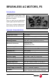
BRUSHLESS AC MOTORS, FS Introduction FS synchronous servo motors (FSA and FSP series) are AC brushless with permanent magnets. They are ideal for any application requiring great positioning accuracy. They have a uniform output torque, high reliability and low maintenance.
. . . FSA02.50F. FSA04.50F. FSA08.50F. . . . FSP02.50F. FSP04.50F. FSP08.50F. 0.95 1.91 3.82 7.16 0.318 0.637 1.27 2.39 7.16 2.39 Nm 3.82 1.27 Nm 1.91 0.637 Mp 0.95 0.318 Mo Nm Nm nmax Io Ip 3000 3000 3000 3000 nmax 4.4 2.8 2.1 0.9 Io 13.4 8.5 6.5 2.8 Ip 3000 3000 3000 3000 5000 5000 5000 5000 4.1 2.6 2.0 0.9 13.9 8.0 6.0 2.
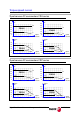
Torque-speed curves Synchronous AC servomotors FSA series Torque Nm Torque Nm 3.0 2.5 1.2 1.0 0.8 0.95 2.0 FSA01 0.6 0.4 1.5 0.2 0 1000 FSA02 1.0 0.318 0.2 0 1.91 2000 3000 4000 5000 0.637 Speed Rev/min 0 0.36 0 Torque Nm 1000 2000 3000 Speed Rev/min 4000 5000 Torque Nm 5.0 10.0 3.82 4.0 8.0 3.0 3.0 2.0 1.27 0.96 1000 2000 3000 5.6 4000 5000 FSA08 4.0 1.6 2.39 1.8 2.0 0.75 0 7.16 6.0 FSA04 1.0 0 0.45 0.5 Speed Rev/min 0 1.
Dimensions Synchronous AC servomotors. FSA series Dimensions Motor length Flange surface Δ brake LR Motor type LM L LL LA LB LC LE LG LZ FSA01 61.5 119.5 94.5 40.5 25 46 30h7 40 2.5 5 4.3 FSA02 63.0 126.5 96.5 39.5 30 70 50h7 60 3 6 5.5 FSA04 91.0 154.5 124.5 39.5 30 70 50h7 60 3 6 5.5 FSA08 111.5 185.0 145.0 44.5 40 90 70h7 80 3 8 7.
Synchronous AC servomotors. FSP series Dimensions Motor length Flange surface Δ brake LR Motor type LM L LL LA LB LC LE LG LZ FSP01 42.5 87 62 29.0 25 70 50h7 60 3 6 5.5 FSP02 48.1 97 67 31.5 30 90 70h7 80 3 8 7 FSP04 68.1 117 87 31.5 30 90 70h7 80 3 8 7 FSP08 66.7 126.5 86.5 33.5 40 145 110h7 120 3.5 10 10 The [Δ brake] column shows the length increment for the L and LL measurements when using a motor configuration “with brake”.
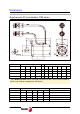
Base power connectors and encoder output The following figure shows the identification of these connectors: 2 2 1 1 Nr 1 2 Connector Base power connector Base feedback connector Note that although the figure shows the FSA series motor, the dimensions of all the connectors will be the same for the FSP series. The base power connector includes pins 4 and 5 of the brake. Remember that it has no polarity and, therefore, the 24 V DC may be applied to either pin.
Viewed from the outside of the motor BASE FEEDBACK CONNECTOR On FSA and FSP motors Pin (200 V) 1 2 3 4 8 Signal 0 V (16 bit absolute) 3.6 V (16 bit absolute) + RS485 - RS485 +5V Color Pink Grey Green Yellow White 9 0V Brown 11 1 10 12 9 16 2 17 13 8 15 4 14 7 6 3 5 Note 1. The rest of pins are not connected Note 2. Connector housing connected to ground Brake characteristics FSA and FSP series motors have an optional brake that applies friction to the shaft.
Sales reference FSA04.50F.J5.000 - S99 MOTOR SERIES MOTOR LENGTH A P LONG MOTORS SHORT MOTORS SIZE/POWER FSP FSA HEIGHT 200 V kW 40 01 0.1 02 04 0.2 60 200 V kW 01 0.1 02 0.2 04 0.4 08 0.75 0.4 80 08 0.
A.C. SERVODRIVE Introduction The MCS Innova Servodrive (MCSi) family is a compact speed servo drive family for controlling small synchronous AC brushless motors. There are three modules of different power offering peak currents of 6.5, 10.5 and 15.0 Arms for single-phase 220 V AC General characteristics Their main characteristics are: 220 V AC single-phase voltage supply. Dynamic braking in case of mains failure. PWM IGBTs Serial encoder feedback. Programmable encoder simulator output.
Model: 101 mm (3.97") 183 mm (7.20") 193.6 mm (7.62") A 163.6 mm (6.44") detail A 180.6 mm (7.11") 6.30 mm (0.24") 6.50 mm (0.25") MCSi 15L Technical data MODELS Rated output current MCSi 07L 2.1 Arms MCSi 11L 3.5 Arms MCSi 15L 5.0 Arms Peak current (3 s) 6.5 Arms 10.5 Arms 15.0 Arms Power supply Consumption Single phase 50/60 Hz. Voltage range between 220-10 % and 230+10 % V AC 12.5 Arms Over-voltage protection 20.0 Arms 29.
Connectors Power terminals Connector X4 POWER INPUTS (L1, L2): Mains input terminals. POWER OUTPUTS (U, V, W): Output terminals for the voltage applied to the motor. Current control with PWM on a carrier frequency of 8 kHz. When connecting to the motor, watch the matching of phases U-U, V-V and W-W. Connector X9 L+, Ri, Re: Terminals to configure and connect the external ballast resistor.
Control signals Conector X3 ANALOG INPUTS AND OUTPUTS Velocity command, pins 1 and 2: Velocity command input for the motor. It admits a range of ± 10 V. PIN 1 PIN 2 Input Input + Programmable analog input, pins 17 and 18: Input for analog command used for some integrated functions. PIN 17 PIN 18 Input Input + ± 12 V, pins 33, 34 and 19: Output of an internal power supply so the user can easily generate a command signal. It offers a maximum current of 20 mA limited internally.
DIRECT FEEDBACK Auxiliary Feedback Input , pins 5, 6, 36, 21, 35, 20, 4 and 3: Input to connect a second feedback device with TTL signals. The connector provides an auxiliary + 5 V DC (0.5 A max) for the feedback device (see pin 4). PIN 6 PIN 5 PIN 21 PIN 36 PIN 20 PIN 35 PIN 3 PIN 4 A+ AB+ BZ+ ZGND + 5 V DC (0.5 A max.) ENABLES Drive Enable input, pin 13: No current circulates through the motor stator winding at 0 V DC, thus it no longer supplies torque. It is activated with +24 V DC.
RELAY FOR INTEGRATED SAFETY Safe-disable relay, pins 41 and 42: Second, normally closed contact (NC) used as an external acknowledgement of the status of the integrated-safety relay. Note that this relay contact must be necessarily included in the electrical maneuver. CHASSIS Metal housing of the connector: Drive chassis connection point. Connector X1 COMMUNICATIONS USB - type A double parallel connector for fast interconnection between various units (ModBus protocol) via RS485 serial line.
Indicators (LED's) +5 V: LED located on top of connector X1. When lit, it indicates that the internal +5 V are being applied. CROWBAR (ON) / VBUS OK: Two-color (green/red) light indicator located next to the + 5 V LED.
Programming module The programming module (present on MCS model) has four numeric displays of 7 segments, a sign indicator and a rotary decoder with a push button for confirmation incorporated on the knob itself. JOG PUSH TO CONFIRM The rotating direction may be: Clockwise being possible to: To scroll through the list of parameters, variables and commands and display a particular one. To increase its value (if parameters). Counterclockwise being possible to: To decrease its value.
There are also a set of variables and certain commands of special characteristics whose meaning and sequences to follow are described in section “initialization and setup” in this manual. Interpretation of the symbols used in some diagrams of this manual. Blinking status of the two rightmost digits of the display. Blinking status of the two leftmost digits of the display. L Long push on the programming module. C Short push on the programming module. Rotary decoder on the programming module.
Top view of the module Terminals to configure and connect the external ballast resistor USB connection with a PC Pinout of the connectors B2 B1 OFF ON A2 A1 B3 A3 B4 A4 COMMUNICATIONS (X1) Pin Signal Description A1, B1 A2, B2 A3, B3 A4, B4 N.C. TxD/RxD - (RS485) TxD/RxD + (RS485) N.C.
1 15 CONTROL SIGNALS (X3) 30 16 44 31 Pin 2 1 18 17 31 32 16 34 33 19 43 44 13 15 14 11 12 27 28 29 30 22 7 24 8 37 38 23 6 5 21 36 20 35 4 3 41 42 Signal I/O ANALOG VELOCITY COMMAND INPUT I PROG. ANALOG INPUT I PROG. ANALOG OUTPUT Description Input + Input Input + Input Programmable analog output 1 O Programmable analog output 2 Range ± 10 V, impedance 56 kΩ Range ± 10 V, impedance 56 kΩ Range ± 10 V GND +12 V (20 mA max) output AUX.
L2 POWER INPUTS & MOTOR (X4) 220V L1 W V Pin Signal Description L2 L1 W V U S phase R phase W phase V phase U phase 220 V mains voltage input terminals. Output terminals for the voltage applied to the motor (200 V). U CONTROL POWER INPUTS (X5) L2 Pin Signal Description 220V L2 L1 S phase R phase Chassis 220 V mains input terminal for the control circuits. L1 Ground SERVICE (X6) 1 2 3 4 5 Pin Signal Description 1 2 3 4 5 N.C. DMO DPO N.C.
INSTALLATION General considerations At the motor Remove the anti-corrosion paint of the shaft before mounting them on to the machine. The motor will admit flange mounts: IM B5 and IMV1. Watch for the ambient conditions mentioned in the section on general characteristics and also: Mount it somewhere that is dry, clean and accesible for maintenance. Remember that the degree of protection is IP55 (standard), shaft section excluded. It must be easily cooled. Avoid corrosive or flammable environments.
>50 mm M6 M6 >30 mm >10 mm >50 mm About the connection All the cables must be shielded, to reduce the interference on the control of the motor due to the commutation of the PWM. The shield of the motor power cable must be connected to the chassis screw at the bottom of the module and it, in turn, taken to mains ground. The command signal lines must be shielded twisted pairs. The shield must be connected to the housing of connector X3. Keep the signal cables away from the power cables.
Power connection. Mains - Drive The drive voltage supply is single phase and does not require a transformer. 220 V AC L2 L1 fuses Autotransformer or single-phase transformer R S T N 380 V AC 220 V AC POWER INPUTS 220 V AC L2 L1 L2 L1 fuses High Floating Voltage X4 k1 power switch X5 2x2.5 mm2 k1 power switch 220 V AC CONTROL POWER INPUT 380 V AC R S T N X5 2x2.5 mm2 X4 L2 L1 POWER INPUTS Autotransformer or single-phase transformer CONTROL POWER INPUT Warning.
Power connection. External Ballast resistor If the application requires a Ballast resistor with a power greater than the one indicated in this table according to model: Internal resistor Ri ----------------45 Ω 60 W Model MCSi 07L MCSi 11L MCSi 15L Maximum power that may be --------15 W External resistor Max. value 65 Ω Min. value 45 Ω therefore: Remove the cable joining the terminals Ri and L+. Install the external resistor between the terminals Re and L+.
Connection Install the proper filter that can handle the sum of the rated Arms currents of the MCSi drives installed in the system. Mains filters FEHV-10Z FEHV-16Z FEHV-30B Imax (A) 10 16 30 Remember that the rated currents of the drives are 2.1 A for the MCSi 07L; 3.5 A for the MCSi 11L and 5 A for the MCSi 15L. Connect the filter using 6.3 mm Faston terminals as shown in the figure.
Mains filters FAGOR FEHV- 30B Power connection. Drive - motor Motor output connector Holding brake (optional) Important: No polarity 24 V DC Released 0 V DC Holding W V U MOTOR X4 Fagor Cables (without brake) MPC 4x0.5 MPC 4x0.5+(2x0.5) (with brake) M 3 MC-15 connector MCSi Drive MCSi-32/84 FSA or FSP motors (220 V) Digital Brushless AC servo drive system - Ref.
Power cables If the motor does not have a brake MPC - 4 x 0.5 If the motor has a brake MPC - 4 x 0.5 + (2 x 0.5) Note: The length of the MPC power cable must be specifically ordered (in meters). Codes of the sales reference of Fagor power cables. E.G. MPC 4 x 0.5 E.G. MPC 4 x 0.5 + (2 x 0.
Connection of the monitoring and control signals Enable signals using 24 V 13 14 15 X3 43 13 44 14 43 Pin Signal 43 44 13 14 15 24 V GND DRIVE ENABLE COMMON SPEED ENABLE 44 15 Signal indicating that the Servodrive is running properly Pin 29 30 Signal DRIVE OK X3 29 DRIVE OK SWITCH 0.6 A - 125 V AC 0.
Monitoring signals Pin Signal 16 31 32 GND PROG. ANALOG. OUT. 1 PROG. ANALOG. OUT. 2 X3 X3 16 16 V 31 32 31 32 V Programmable digital outputs + 24 V DC + 24 V DC X3 Collector 27 28 Emitter Maximum current 100 mA Maximum voltage 50 V Pin Signal 27 28 PROG. DIGIT. OUT (C) PROG. DIGIT. OUT. (E) X3 Collector 28 27 28 Emitter X3 Programmable digital input X3 Pin Signal 11 12 PROG. DIGIT. INPUT COMMON PROG. DIGIT.
Encoder feedback connection The signals generated by the encoder are taken to connector (X2) FEEDBACK INPUT of the MCSi drive. The MCS amplifies these signals and may divide their frequency. The division factor is given by the values of parameter EP1 and the sequence between A and B by parameter EP3. The MCPi drive outputs these signals through (X3) CONTROL SIGNALS. The encoder must be mounted on to the motor shaft and cannot be installed anywhere else in the transmission chain.
Analog command signal connection The command governing the motor may be a velocity or current command. All the command signal lines must be shielded twisted pairs. The shield must be connected to the housing of the 44-pin connector X3 (control signals). The input impedance of the velocity command is 56 KΩ (a range ±10V). Differential velocity command input Range of ±10 V Uref.
Diagram of the electrical cabinet This is an orientative diagram for the installation of the electrical cabinet. This diagram may be modified according to the requirements of each application. It includes a simple circuit for the voltage supply of the brake of the servo motors. The use of fuses is a must. Mains connection and maneuver diagram The delayed disconnection of D3 contacts is useful so: The Drive Enable stays active while the motor brakes at maximum torque.
Integrated safety The Safe Disable function (SD) offered by Fagor MCS Innova drives permits disabling the power output of the drive making sure that the motor torque is eliminated as a safe situation. This function is available through the "Drive Enable" section so called in standard Fagor servo drive systems. Techniques and elements approved to be used in safety systems have been considered for its design and internal operation.
The following figure shows the diagram of the safe disable (SD) of an MCS Innova and as an example of application, a diagram to control the access to areas with moving elements: Diagram to control the access to areas with moving elements Integrated-safety relay Mains T S R Work Zone 1 Work Zone 2 M Inductance MCS Innova L2 L1 S2 S1 { MCS Innova Drive Enable Pin 13 (X3) CONTROL Safety Relay Pins 41 & 42 (X3) Inductance L1 DRIVE 1 DRIVE 2 DRIVE 3 DRIVE 4 MCS Innova Pin 41 (X3) Pin 42 (X3)
Initialization and adjustment After starting the motor-drive system, the way the parameters, variables and commands will be displayed and edited will be determined by the access level: Fagor level, user level or basic level restricting, depending on the level, the access to some or all of them. This access level is determined by entering its corresponding code in the GV7 variable.
Once the GC10 has been found (by turning the decoder until appears on the display) the sequence to follow is shown in the figure: C C C L NO ok? C When doing a reset, all these modifications will be ignored because on startup the drive restores the configuration stored in its E2PROM memory. YES C C C L NO ok? C YES All that has been done so far is saved in the RAM memory of the drive, but not permanently.
If the command has been executed properly, the displays shows the word: dOnE. Otherwise, in case of an error, it displays the word: Err. In any of these instances, a short push returns it to its initial state.
On the other hand, when adjusting it, proceed as follows: Verify that desired velocity or current command is selected. To do this, make sure that all the parameters involved (such as SP45, etc.) are properly set. When using external analog command, verify that it is output to the proper pins. Note: When using an analog command, set parameters SP20 and SP21 properly to obtain the desired response to the velocity command entered.
The first time the unit is connected to the PC, the operating system will show two messages indicating that “new hardware has been detected”. Do the installation, recommended by the system and ignore the message regarding the incompatibility tests of the software with the operating system Windows® XP that comes up during the installation process. Go on by pressing the button. This message refers to the drives that have not been certified yet. However, they are fully functional.
PARAMETERS, VARIABLES AND COMMANDS NOTATION USED [Group] [Type] [Index] where: Group: Identifying character of the logic group to which the parameter or variable belongs. There are the following groups of parameters: GROUPS OF PARAMETERS, VARIABLES & COMMANDS Nr 1 2 3 4 5 6 7 8 9 10 11 12 13 14 15 FUNCTION GROUP LETTER Control signals Terminal box B Current control loop Current.
Access level: The access level is defined by the number following the ID: Thus: Fagor level User level Basic level Examples of access levels SP10 basic CV11 Fagor, RO S group (P) parameter nr (10) C group (V) variable nr (11) (RO) read-only variable. (basic) access level (Fagor) access level Modifiable variable: Any modifiable variable, in other words, that can be read and written, will carry the (RW) label to identify it as such next to its access level.
B group. Non-programmable inputs - outputs BV14 FAGOR, RO Function: NotProgrammableIOs Indicates the logic values of the electrical control signals of the drive. 24 V at the electrical input mean a logic 1 at the bits of this variable. Bit 15, ...
CP10 USER, RW Function: VoltageAmpVolt Parameters CP10 and CP11 define the relationship between the voltage of the analog input IV2 and the current that this input generates in IV3. V CP10 CP11 A Valid values: 1.000, ..., 9.999 V. Default value: 9.500 V. CP11 USER, RW AmpAmpVolt Function: See parameter CP10. Valid values: 1.00, ..., 50.00 A. Depends on the connected drive. Default value: MP3. Rated motor current (in amperes).
CP31 FAGOR, RW CurrentCommandFilter1Frequency Function: Sets the natural frequency in Hz of a notch filter that acts upon the current command. Valid values: 0, ..., 4000. Default value: 0. CP32 FAGOR, RW CurrentCommandFilter1Damping Function: Sets the bandwidth in Hz of a notch filter that acts upon the current command. Valid values: 0, ..., 1000. Default value: 0. CP45 USER, RW CurrentCommandSelector Function: This parameter is used to determine the command source of the current loop.
3 External analog. It applies the value of the external auxiliary input ( pins 17 and 18 of connector X3 ) after being treated, IV3, if IP17 has the right value (IP17 = 1). WV5 WV4 0 1 2 0 From the velocity loop From the functions generator CV15 Digital Command CP45 1 2 0 IP17 IV3 1 Analog Command Default value: CV1 USER, RO 3 2 0. Current1Feedback Function: Display the value of the feedback of the current going through phase V. Valid values: - 50, ...+ 50 A (instant values).
CV10 FAGOR, RO Current1Offset Function: Value of the automatic compensation of the current feedback offset of phase V. Valid values: - 2000, ..., + 2000 mA (depends on the connected drive). Default value: 0. CV11 FAGOR, RO Current2Offset Function: Value of the automatic compensation of the current feedback offset of phase W. Valid values: - 2000, ..., + 2000 mA (depends on the connected drive). Default value: 0.
DV31 FAGOR, RO Function: DriveStatusWord The DV31 variable contains a numerical data coded into 16 binary bits and represents the system status as shown by the attached table. Bits (from the most to the least significant). Bit Function 15, 14 Power & Torque Status. (0,0) DoingInternalTest (DRVSTS_INITIALIZATING) (0,1) ReadyForPower (DRVSTS_LBUS) (1,0) PowerOn (DRSTS_POWER_ON) (1,1) TorqueOn (DRSTS_TORQUE_ON). 13 Error bit 12 Warning 11 OperationStatusChangeBit 10...
DC2 USER, RW Function: ResetHistoricOfErrors Reset of the DV17 variable HistoricOfErrors (array). This command sets it to 0. E group. Encoder simulator EP1 BASIC, RW EncoderSimulatorPulsesPerTurn Function: Number of pulses generated by the encoder simulator per rotor revolution. Valid values: 1, ..., Number of pulses of the selected feedback. Default value: Number of pulses of the selected feedback device.
GP9 BASIC, RW DriveOffDelayTime Function: After the motor has stopped because the Speed_Enable function has been disabled, the cancellation of the the Drive_Enable function (that implies PWM-OFF) is delayed by a time period indicated by GP9. It is useful on axes not compensated with a holding brake. To make this time period infinite, set it to 0 and to remove it, set it to 1. Valid values: 1, ..., 9999 ms, 0 (infinite). Default value: 50 ms.
GV11 BASIC, RW SoftReset Function: Variable that resets the unit by software. Valid values: 0 and 1 (with 1, it resets the unit). Default value: 0. GV16 USER, RO Function: GV75 MotorTableVersion Version of the motor table. FAGOR, RO ErrorList Function: List of the error numbers active in the unit. Valid values: 0, ..., 999. Default value: 0. GC1 BASIC, RW Function: GC10 BackupWorkingMemoryCommand Command to execute the parameter transfer from RAM to E2PROM.
I group. Inputs IP6 USER, RW DigitalInputPolarity Function: Sets the polarity (inverted or not inverted) of the programmable input (pins 11 and 12 of X3). Valid values: 0. Not inverted. 1. Inverted. Default value: 0. Not inverted. X3.11 PROG_DIGIT_INPUT X3.12 IP14 USER, RW 1 IP6 IV10 0 DigitalInputFunctionSelector Function: Determines the function assigned to the digital input of the unit.
IP17 USER, RW AnalogFunctionSelector Function: Determines the analog function assigned to the programmable analog input. Valid values: 0, ..., 2. Default value: 0. IP17 00 01 02 IV3 as input to function Nr IV1 BASIC, RO Function: Function -------Func1 Func2 AnalogInput1 Monitors the voltage through the analog input ANALOG VELOCITY COMMAND INPUT (VEL+ and VEL-) (pins 2 - 1 of X3). It's display is in volts. VEL + X3.2 X3.18 16 Bit VEL - X3.1 IV1 X3.17 12 Bit IV2 PROG. ANALOG. INPUT X3.
IV10 USER, RO DigitalInputs Function: This variable reflects the status of the programmable digital input at pins 11 and 12 of connector X3. The status of this variable is affected by IP6. Valid values: 0 and 1. Default value: 0. K group. Monitoring KP3 USER, RW ExtBallastPower Function: Contains the value of power of the external ballast resistor. Valid values: 200, ..., 2000 W. Default value: 200 W.
KV36 USER, RO I2tMotor Function: Variable internally useful to the system. It measures the internal load level of the calculation of the i2t at the motor in percentage used over the maximum. Valid values: 0, ..., 100 %. Default value: 0 %. KV40 USER, RO IntBallastOverload Function: Shows the load percentage on the ballast resistor in a drive. Useful for the i2t protection of the resistor. A value greater than 100 % in this variable causes error E314. Valid values: 0, ..., 100 %.
MP2 FAGOR, RW MotorTorqueConstant Function: Contains the torque constant of the synchronous motor, (motor torque according to the rms current) Valid values: 0.0, ..., 10.0 Nm/Arms. Default value: It depends on the motor connected. MP3 FAGOR, RW MotorContinuousStallCurrent Function: Contains the motor rated current. Manipulating MP3 may affect parameter CP20 directly. See parameter CP20. Valid values: 0.00, ..., 50.00 Arms. Depends on the motor connected.
OP1 VARIABLE NAME OP2 VARIABLE 00 SV15 DigitalVelocityCommand 00 SV15 01 SV1 VelocityCommand 01 SV1 02 SV6 VelocityCommandAfterFilters 02 SV6 03 SV7 VelocityCommandFinal 03 SV7 04 SV2 VelocityFeedback 04 SV2 05 TV1 TorqueCommand 05 TV1 06 TV2 TorqueFeedback 06 TV2 07 CV3 CurrentFeedback 07 CV3 cA 08 WV5 GeneratorOutput 08 WV5 ------- 09 IV1 AnalogInput1 09 IV1 10 IV2 AnalogInput2 10 IV2 11 Reserved Reserved 11 Reserved OP3 USER, RW DA1Valu
X3.27 OV10 1 OP6 0 X3.28 OP14 USER, RW Function: DigitalOutputFunctionSelector They determine the activation of the various outputs of the digital functions available. OP14 00 01 02 03 04 05 06 07 OP15 USER, RW function OutFunc0 OutFunc1 OutFunc2 OutFunc3 OutFunc4 OutFunc5 OutFunc6 OutFunc7 OV10 as output of function Nr DigitalOutputWarningSelector Function: Selector of the warning that will be displayed by the programmable output when function OutFunc7 is selected. Valid values: 0.
OV10 USER, RO DigitalOutputs Function: The OV10 variable contains the value of the output status of the various functions that may be selected with OP14. Valid values: 0 and 1. Default value: 0. Q group. Communication QP16 USER, RW Function: Default value: SerialSettings Determines the communications parameters of the UART (Universal Asynchronous Receiver/Transmitter) of the 485 serial line of connector X1.
C A long push at any of the fields validates the value of parameter QP16 L It goes into modifying modifica the selected field. The display blinks. A long push validates the value shown by the display L C L C L C L C Successive rotations scroll the posible values of the field QV22 FAGOR, RO IDNListOfInvalidOperationData Function: Variable containing the parameters that are readjusted by the drive when it issues the error E.502 (incompatible parameters).
S group. Speed SP1 BASIC, RW VelocityProportionalGain SP2 BASIC, RW VelocityIntegralGain Function: Value of the proportional / integral action of the velocity PI. Valid values: SP1: 0, ..., 999.9 mArms/rpm. SP2: 0.1, ..., 999.9 ms. Default value: Depends on the motor-drive combination. SP1 SP2 SP2 SP1 SP3 BASIC, RW VelocityDerivativeGain Function: Value of the derivative action of the velocity PI. Valid values: SP3: 0, ..., 9999. Default value: SP1: 0.
SP19 BASIC, RW SymmetryCorrection Function: Its purpose is to correct the possible difference in analog command generated to obtain exactly the same speed in both turning directions. Valid values: Default value: - 500, ..., + 500 mV 0 mV. SP20 BASIC, RW SP19 VoltageRpmVolt Function: Parameter SP20 and SP21 set the necessary ratio between the analog command and the motor speed. They correspond to the reference of the CNC concept G00 Feed. Valid values: Default value: 1.00, ...,10.00 V. 9.50 V.
SP40 USER, RW VelocityThresholdNx Function: Velocity level over which the OV10 variable is activated when function OutFunc3 (MotorSpeed > SP40) is active. Valid values: 0, ..., Motor rated speed (rev/min). Default value: 1000 rev/min. SP41 USER, RW VelocityWindow Function: Velocity window assigned to the "reached speed" function. It is used to know when the speed of a motor (SV2) has reached the supplied command (SV7) within the margins of this window SP41. Valid values: 0, ...
SP45 BASIC, RW VelocityCommandSelector Function: This parameter is used to determine the velocity command source. Valid values: 0, ..., 2. value 0 function Analog. Input through pins 1 and 2 of connector X3 after being adapted by SP19, SP20 and SP21. Function generator. Value of WV5 if the output of the function generator is applied to the velocity loop (WV4=1). Digital. Value of SV15. 1 2 Default value: 0.
SP65 BASIC, RW Function: EmergencyAcceleration In emergency stop. If the bus voltage drops or there is a power outage for the unit in the acceleration, deceleration or constant power mode, the drive will get into the dynamic braking sequence. It stops with the emergency ramp until its speed is zero as long as the mechanical energy stored in the motor allows it. Therefore, it limits the command acceleration for stopping the motor.
SV1 BASIC, RW VelocityCommand Function: Velocity command after the SP45 selector. Valid values: - 6000, ..., + 6000 rev/min. Default value: 0. SV2 BASIC, RO VelocityFeedback Function: Velocity feedback. Valid values: - 9999, ..., + 9999 rev/min. SV6 BASIC, RO VelocityCommandAfterFilters Function: Velocity command after applying limits, ramps, etc. Valid values: - 9999, ..., + 9999 rev/min. SV7 BASIC, RO VelocityCommandFinal Function: Final velocity command applied to the loop.
TV1 USER, RO TorqueCommand TV2 USER, RO TorqueFeedback Function: Displays the values of the command and torque feedback. Valid values: Default value: - 99.9..., + 99.9 Nm 0 Nm. TV1 TV2 _D_rel W group. Internal generator WV1 USER, RW Function: GeneratorShape It indicates the waveform of the internal command generator. Valid values: Value 0 1 2 Default value: WV2 USER, RW Waveform sinusoidal square triangular 1.
WV4 USER, RW Function: It specifies on which magnitude the internal command is applied. Valid values: Default value: WV5 GeneratorType USER, RO Value 0 1 2 Waveform generated disconnected (by default) generated connected. Velocity command generated connected. Current command 0. GeneratorOutput Function: Variable that reflects the value of the signal generated by the internal function generator. Valid values: - 9999, ..., + 9999. Default value: 0.
ERROR MESSAGES E.001 Internal Contact Fagor Automation. E.003 Error at the power bus voltage Error When having torque, one of the phases of the line may have dropped. Warning: When starting the unit up, maybe: The connector of the Ballast resistor has not been installed. The Ballast resistor is open. Check that the line phases and the drives are OK in the direction indicated earlier and start the system back up. 1, 2 or 3 lines lost 1 line lost Power Supply Drive Enable BV14.0 Speed Enable BV14.
Solutions The load that must stop the motor is too large to stop it in the time frame set by GP3 and the value given to this parameter must be increased. The threshold or velocity window considered zero (SP42) is too small; thus, increase the value ofthis parameter. The module is performing poorly and is unable to stop the motor. The module may be defective. If t1 < GP3 then after GP9 motor torque ON = 0; else (motor torque ON = 0 and “E.004”) t1 GP9 SV2 SP42 Time E.
E.200 Overspeed Speed SV2 1.12 x Rated Motor Speed Rated Motor Speed “E.200” The motor speed has exceeded the value of SP10 in a 12 %. Bad cabling of the position sensor or of the motor power. The velocity loop is adjusted wrong. Decrease the speed overshoot in the system response. Time E.201 Motor overload E.202 Drive overload The I2t protection of the drive went off. The duty cycle is greater than the system can provide. Decrease the speed overshoot in the system response.
E.214 Short-circuit There is short-circuit at the drive module. Reset the error. If it persists, may be because: An erroneous sequence when connecting the power cables or a shortcircuit between them. The parameters may be wrong or there is a fault at the drive. Contact Fagor Automation. After displaying E.214, it will display some of the codes that describe the type of short-circuit that has taken place. ABS IGBT OUT E.
E.502 Incompatible parameters Parameter incompatibility. Example. A drive controls a motor that admits a peak current of 20 A (e.g.: being the current limit CP20 = 20 A). If now, a 16A peak motor is connected, the current limit will be beyond the value allowed for this new motor. It will readjust in RAM memory certain parameters related to speed and current issuing E502 and describing the erroneous parameters in the QV22 variable.
WARNINGS The warnings indicate that the drive is approaching an error limit. Thus: Before the drive display shows errors E.201, E.202 and E.314, it will issue a warning with fast flashing (0.5 s) of the BUS ACTIVITY indicator. If this behavior continues for longer than 5 s, the display will show one of the errors mentioned earlier. Warning W.003. Warning due to a drive power-up failure. It will appear in the following circumstances.
LIST OF PARAMETERS, VARIABLES & COMMANDS. MODBUS ID’S Mnem. Name Level IdBus Ac Min. Max. Def.
Mnem. Name Level IdBus Ac Min. Max. Def.
Mnem. Name Level IdBus Ac Min. Max. Def.
User notes: Digital Brushless AC servo drive system - Ref.
Fagor subsidiaries: SPAIN Headquarters: PORTUGAL Nanjing: FAGOR AUTOMATION LTDA. Sucursal Portuguesa Rua Gonçalves Zarco nº 1129-B-2º Salas 210/212 4450 LEÇA DA PALMEIRA Tel: 351 22 996 88 65 Fax: 351 22 996 07 19 E-mail: fagorautomation@fagorautomation.pt FAGOR AUTOMATION EQUIPMENT LTD. NANJING OFFICE Room 803, Holiday Inn (Nanjing) 45 Zhongshan Beilu, 210008 NANJING, P.R. CHINA Tel: 86-25-83328259 Fax: 86-25-83328260 E-mail: fagor_nj@fagorautomation.com.
VELOCITY CONTROL BLOCK DIAGRAM GENERAL PARAMETERS DRIVE ENABLE GV2 GV7 Software version GC10 GC11 X3.29 L. buS [.] Waiting P. Supply Default parameters Reset [rdy1] [rdy0] Motor running Motor running speed = 0 GC1 Store parameters [rdy-] Drive Enable (on) and no pulses GV9 Drive type GV5 Code Checksum Password ERR0R DESCRIPTION E.001 Watch dog DR. OK DISPLAY DRIVE STATUS X3.30 Drive ready X3.13 PULSES SPEED ENABLE X3.15 MOTOR TORQUE ON COMMON X3.14 SP20 & SP21 E.
I/O FUNCTIONS FUNCTION OP14 NO FUNC. OUTFUNC1 00 01 OUTFUNC2 02 OUTFUNC3 OUTFUNC4 OUTFUNC5 OUTFUNC6 OUTFUNC7 03 04 05 06 07 X3.11 PROG DIG INPUT IP14 IP6 IV10 0 X3.12 IP14 01 IV10 as input to function nr: FUNCTION 00 01 INFUNC0 02 03 INFUNC2 INFUNC3 04 INFUNC4 INFUNC1 IV10 REMOTE P. / P.I. CONTROL OV10 as output from function nr: OV10 X3.27 1 OP6 PROG DIGIT OUTPUT 0 X3.
ANALOG FUNCTIONS CP10, CP11 PROG ANALOG INPUT IP17 Voltage CP10 X3.17 IV3 as input to function nr: IV3 IV2 X3.18 CP11 Function NO FUNC.
ERROR FUNCTIONS Function "E.106" Power Supply fault Function "E.003" OverSpeed speed KV2 1 line lost 1, 2 or 3 lines lost Function "E.200" Drive Overtemperature SV2 Tensión de alimentación Motor rated speed 105 ºC Drive Enable x 1.12 Motor rated speed "E.106" Speed Enable "E.003" "E.200" time Function "E.201" time Motor Overload time Function " E.202 " time Drive Overload Function " E.