instruction manual AXP-AI8 Eight-Channel Analog Input Interface Board C u s t o m Pa n e l I n t e r f a c e s
AMX Limited Warranty and Disclaimer AMX Corporation warrants its products to be free of defects in material and workmanship under normal use for three (3) years from the date of purchase from AMX Corporation, with the following exceptions: • Electroluminescent and LCD Control Panels are warranted for three (3) years, except for the display and touch overlay components that are warranted for a period of one (1) year.
Table of Contents Table of Contents Product Information .................................................................................................1 Specifications .................................................................................................................... 1 Dimensions and Descriptions............................................................................................ 2 Installation ......................................................................................
Table of Contents ii AXP-AI8 Eight-Channel Analog Interface Board
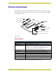
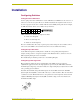
Product Information Product Information The AMX Eight-Channel Analog Input Interface Board (AXP-AI8) is a 10-bit analog-to-digital interface board used to integrate remote analog sources, such as joysticks or potentiometers (POTs), with AMX Axcess systems. AXLink connector AXLink Status LED Input On/Off SIP Switch Device DIP Switch HI/LO Reference POTs 20-pin Header Connect this side to PC board. Connect this side to ribbon cable. FIG.
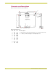
Product Information Dimensions and Descriptions FIG. 2 shows the dimensions of the AXP-AI8: H B C A AXlink AXlink L PWR AXP AXM GND A P1 Top View (Component Side) D E G 2 1 F P2 A 20 19 J K min FIG. 2 AXP-AI8 dimensions 2 Item Inch mm A 0.20 5.10 G 20-Pin Header - .025 inch (6 mm) square pins, .1 inch (2.4 mm) typical spacing. H .125 inch (3.2 mm) mounting holes for #4-40 (3 mm) screws. B 3.50 88.90 C 3.10 78.70 D 2.75 69.90 E 2.35 59.70 F 1.10 27.94 J 0.23 5.
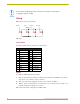
Installation Installation Configuring Switches Setting the Device DIP Switch Use the eight-position device DIP switch to set the AXP-AI8 as an AXlink device. It can be one of 255 devices in an Axcess system. The device number must match the assignment of the device in the Axcess program. Set the device number with the total of all ON (down) positions. For example, the DIP switch below defines device number 129 (1+128=129).
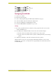
Installation Be sure that the board input ground is connected to the voltage source ground prior to applying a voltage to the input. Wiring FIG. 4 shows typical joystick wiring: Tilt 4 Pan 2 Pan 2 Tilt 4 Zoom 6 Zoom 6 Focus 8 Focus 8 GND 17,18 GND 17, 18 +5+5V VDC DCREF REF19,20 19,20 FIG.
Installation PWR PWR AXP AXP AXM AXM GND GND PWR PWR AXP AXP AXM AXM SYSTEM System GND GND FIG. 5 AXlink wiring diagram Configuring the AXP-AI8 1. Set the device number. 2. Turn off any unused inputs. 3. Create a wiring diagram using the AXP-AI8 System Worksheet on page 7. 4. Connect the ribbon cable or the PC board to 20-pin header. 5. Connect the AXP-AI8 to the AXlink data/power bus. 6. Check the AXlink LED. It should blink once per second. Testing 1.
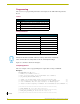
Installation Programming This section covers programming information and examples for the AXP-AI8 Analog Interface Board. Levels Levels Level Function 1 Voltage output channel 1 and joystick/slider control (0 - 255). 5 Voltage input channel 1 (0 - 255). 2 Voltage output channel 2 and joystick/slider control (0 - 255). 6 Voltage input channel 2 (0 - 255). Send_Commands Send_Commands SEND COMMAND AI8,"'DELTA5'" Puts channel 5 in delta mode. SEND COMMAND AI8,"'DELTA6'" Puts channel 6 in delta mode.
Installation (* ORPHAN_FILE_PLATFORM: 1 *) (***********************************************************) (*!!FILE REVISION: Rev 0 *) (* REVISION DATE: 04/24/2001 *) (* *) (* COMMENTS: *) (* *) (***********************************************************) (*}}PS_SOURCE_INFO *) (***********************************************************) (* DEVICE NUMBER DEFINITIONS GO BELOW *) (***********************************************************) DEFINE_DEVICE AI8 = 64 (* EIGHT INPUT ANALOG BOARD *) TP = 128 (* TOU
Installation CREATE_LEVEL AI8,2,IN2 (* INPUT WITH A VARIABLE NAME *) CREATE_LEVEL AI8,3,IN3 (* IN WHICH TO STORE THE INPUT *) CREATE_LEVEL AI8,4,IN4 (* ANALOG VALUE (LEVEL) *) CREATE_LEVEL AI8,5,IN5 CREATE_LEVEL AI8,6,IN6 CREATE_LEVEL AI8,7,IN7 CREATE_LEVEL AI8,8,IN8 (* CREATE_LEVEL AI8,1,IN1[1] (* HERE WE ASSOCIATE EACH AI8 *) CREATE_LEVEL AI8,2,IN2[1] (* INPUT WITH A VARIABLE NAME *) CREATE_LEVEL AI8,3,IN3[1] (* IN WHICH TO STORE THE INPUT *) CREATE_LEVEL AI8,4,IN4[1] (* ANALOG VALUE (LEVEL) *) CREATE_LE
System Worksheet System Worksheet Dealer ID #: Dealer: _______________________________________ Date: _____________________________________________ ________________________________________ PO#: __________________________________________ Job: ______________________________________________ SO#: _____________________________________________ Description: ________________________________________ Serial #: ___________________________________________ Rev# : ____________________________________________ Devi
brussels • dallas • los angeles • mexico city • philadelphia • shanghai • singapore • tampa • toronto* • york 3000 research drive, richardson, TX 75082 USA • 469.624.8000 • 800.222.0193 • fax 469.624.7153 • technical support 800.932.6993 038-004-1034 12/03 ©2003 AMX Corporation. All rights reserved. AMX, the AMX logo, the building icon, the home icon, and the light bulb icon are all trademarks of AMX Corporation. AMX reserves the right to alter specifications without notice at any time.