instruction manual AXB-232++ RS-232/422/485 Interface AXlink Bus Controllers
Table of Contents Table of Contents Product Information .................................................................................................1 Front Panel........................................................................................................................ 1 Rear Panel ........................................................................................................................ 1 Specifications .........................................................................
Table of Contents ii AXB-232++ RS-232/422/485 Interface
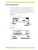
Product Information Product Information The AXB-232++ RS-232/422/485 Interface is an AXlink bus controller that provides remote control for devices that require a variety of control protocols. The AXB-232++ extends RS-232, RS-422, or RS-485 control to remote sources over the 4-wire AXlink data/power bus. Onboard processing and memory allows the controller to take on complex tasks by itself, reducing the processing burden for the Axcess control system.
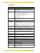
Product Information Specifications The following table lists the specifications for the AXB-232++. Specifications Power 12 VDC @ 160 mA Processor On board 32-bit processor and 384K (of non-volatile memory) run Axcess programs independent of the control system. This relieves the AXlink bus and controller for the processing time for controlling those devices. (Requires Axcess Version 3.0 or higher.) Asynchronous data standards • Baud rates - 300, 600, 1200. 2400, 4800, 9600, 19200 and 38400.
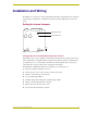
Installation and Wiring Installation and Wiring The AXB-232++ can be used as an independent RS-232/422/485-controlled interface by setting the internal jumpers. Configure the communication parameters using the DIP switches on the front panel. Setting the Internal Jumpers JP4 Internal jumper JP4 Internal jumper JP5 JP5 CORP. 1998 front AXB-232++ FIG.
Installation and Wiring Setting jumper JP5 to set the RS-422 port for RS-485 use 1. Disconnect the RS-232/422/485 connectors. 2. Unscrew the two screws on the rear panel, and remove the panel. 3. Slide the circuit board out of the enclosure. 4. Locate the JP5 jumper (see FIG. 3 on page 3). 5. Set jumper JP5 to the ON position (the default setting is OFF). 6. Slide the circuit board back into the enclosure. 7. Replace the panel, and refasten the screws. 8. Reconnect the RS-232/422/485 connectors.
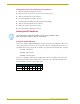
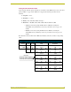
Installation and Wiring Setting the RS-232/422 DIP switch Set the stop bits, data bits, parity, and baud rate on the RS-232/422 DIP switch, located on the front panel (see FIG. 1 on page 1). The AXB-232++ supports the following asynchronous data standards: Stop bits 1 and 2 Data bits 7, 8, and 9 Parity None, Odd, Even, Mark, and Space Baud rates 300, 600, 1,200, 2,400, 4,800, 9,600, 19,200 and 38,400.
Installation and Wiring Wiring Devices to the AXB-232++ Preparing captive wires To connect the wiring into a captive-wire connector: 1. Strip 1/4 inch off the wire insulation for all four wires. 2. Tin 2/3 of the exposed wire. 3. Insert each wire into the appropriate captive-wire connector up to the insulation. 4. Tighten the captive screws to secure the fit in the connector. If the device is using a separate power supply, do not connect the power wiring from the AXB-232++ to that device.
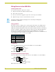
Installation and Wiring Using RS-232 When communicating via RS-232, connect the wiring as shown in FIG. 6. AXB232++ GND RX TX GND RX Device TX +12V RX RX + TX TX + FIG. 6 RS-232 wiring Using Hardware Handshaking When the controlled device requires hardware handshaking, connect the wiring as shown in FIG. 7. 1 AXB-232++ 2 3 4 CTS RTS RTS CTS Device FIG. 7 Hardware handshaking wiring Using RS-422 When communicating via RS-422, connect the wiring as shown in FIG. 8.
Installation and Wiring Rack-mounting the AXB-232++ (optional) To rack-mount the AXB-232++ into the optional AC-RK Accessory Rack Kit: 1. Remove any connected power, and AXlink and RS-232 connectors from the rear panel. 2. Remove the two screws on the front panel of the AXB-232++. 3. Remove the front panel and space bracket behind the panel. 4. Place the unit in the appropriate opening in the AC-RK. 5. Place the front panel of the AXB-232++ on the front of the rack, over the unit. 6.
Programming Programming Send_Commands The AXB-232++ supports the same command set as the AXC-232. The following table lists the AXB-232++ Send_Commands. AXB-232++ Send_Commands B9MOFF Sets data bit mode to normal with DIP switch settings (default). Syntax: 'B9MOFF' Example: SEND_COMMAND AXB232,'B9MOFF' Sets the data bit mode to normal. B9MON Enables a special mode to override DIP switch settings. Syntax: 'B9MON' The mode, nine data bits with one stop bit, overrides the data, stop, and parity settings.
Programming AXB-232++ Send_Commands (Cont.) CHARD Syntax: Sets delay between all transmitted characters to the increment specified. Variable: 'CHARD-
Programming AXB-232++ Send_Commands (Cont.) RXOFF Syntax: AXB-232++ does not pass on 'RXOFF' received characters to the Example: Master (default). SEND_COMMAND AXB232,'RXOFF' AXB-232++ does not pass on received characters to the master. RXON Syntax: Enables AXB-232++ to send 'RXON' incoming characters received Example: to the Master. SEND_COMMAND AXB232,'RXON' Enables AXB-232++ to send incoming characters received to the master.
Programming Send_String Escape Sequences The AXB-232++ does not regard certain three-character combinations within a Send_String program as literal characters, but as commands. The following table lists those combinations. Send_String Escape Sequences 27,17,
Programming AXB-232++ Program Statements The Axcess program of the AXB-232++ communicates with the master as Device 0. Its device communicates with the RS232/422 Input/Output (I/O) of the AXB-232++ as Device 1. The following table lists AXB-232++ statements. AXB-232++ Program Statements Statement Function CREATE_BUFFER 0,buffer Places strings that come from the Master into buffer. If no CREATE_BUFFER 0 exists, the incoming strings from the Master are sent out the RS232 port.
Programming Xmodem Timing Commands The following table lists the AXB-232++ Xmodem timing commands. Xmodem timeouts exist to accommodate potential Ethernet delays and for consistency among and within products. Any Xmodem timing command will change timing and retries for Axcess code download as well as Softrom transfer. Xmodem Timing Commands Command Description 'TIMEOUT XX' Xmodem timeouts via the Program Port. (Default is 10 sec.
Programming Reserved Channels The following table lists the channels reserved on Device 0. Reserved Channels Channel Function Channel 254 This is only valid within the device and is not sent to the AXlink Master. Reflects AXlink status: • When AXlink is active, this channel is on. • When AXlink is inactive, this channel is off. • When this channel changes state, the AXB-232++ generates a PUSH or RELEASE. Channel 255 Reflects the state of the CTS input.
ARGENTINA • AUSTRALIA • BELGIUM • BRAZIL • CANADA • CHINA • ENGLAND • FRANCE • GERMANY • GREECE • HONG KONG • INDIA • INDONESIA • ITALY • JAPAN LEBANON • MALAYSIA • MEXICO • NETHERLANDS • NEW ZEALAND • PHILIPPINES • PORTUGAL • RUSSIA • SINGAPORE • SPAIN • SWITZERLAND • THAILAND • TURKEY • USA ATLANTA • BOSTON • CHICAGO • CLEVELAND • DALLAS • DENVER • INDIANAPOLIS • LOS ANGELES • MINNEAPOLIS • PHILADELPHIA • PHOENIX • PORTLAND • SPOKANE • TAMPA 3000 RESEARCH DRIVE, RICHARDSON, TX 75082 USA • 800.222.