
Specifications


Electronic Modules Ver. 0002 EM - 41
Dip-Switches.
The status of the Dip-Switch (DS1, DS2) MUST NOT be changed by the operator.
Adjustment outputs (pins 6 and 7)
With these outputs and a potentiometer, the user can obtain a variable analog voltage for
adjusting the servo system during setup. The voltage, with no load, at these pins is ±15
Vdc.
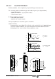
The figure below shows the electrical circuit necessary to obtain the reference voltage.
The table next to it shows the resistor values recommended for a Vref voltage range of
about ±10 Vdc.
Analog outputs (pins 8-9 and 10-11)
These outputs provide the status of the two internal system variables with an analog
value. They are especially designed to be connected to an oscilloscope and facilitate
system setup or to continuously monitor those internal variables.
Note: If the output current is high, the voltage range may decrease.
The parameters controlling these analog outputs are OP1 -F01400-, OP2 -F01401-,
OP3 -F01402- and OP4 -F01403-. The internal variables (speed reference, Actual
speed, torque, etc.) that can be associated with each one of the outputs are set by
means of the monitor program for PC-Windows supplied by Fagor: "DDS-SETUP". See
chapter SSU.
5
4
1
7
+15 Vdc
X7
GND
Vref
R'
R'
Rext
DRIVE
1 KOhms 0 Ohms
5 KOhms 820 Ohms
10 KOhms
20 KOhms
Rext R'
±10 Volt Range
=>
=>
=>
=>
=>
6
-15 Vdc
8
10
1.8 KOhms
3.3 KOhms
Analog Outputs Characteristics
Resolution 4.88 mV
Voltage range ±10 Vdc
Maximum current ±15 mA
Impedance (respect to GND) 112 Ohms