
Specifications


EM - 40 Electronic Modules Ver. 0002
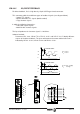
Analog input 1 (pins 4 and 5)
It is the usual input for the velocity command (±10Vdc) generated by the CNC.
The initial offset adjustment is made through parameter SP30 -F01603-.
Later adjustments may be made with potentiometer P1.
Analog input 2 (pins 2 and 3)
This is an input for an auxiliary command.
The initial offset adjustment is made through parameter SP31 -F01604-.
Later adjustments may be made with potentiometer P2.
Variables IV1 -F00905- AnalogInput1 and IV2 -F00906- AnalogInput2 register the value of these
analog inputs at all times. Parameter IP1 -F00900- selects which of these inputs is considered
by the drive as its velocity command.
Parameter SP20 -F00031- and SP21 -F00081- set the relationship between the voltage
applied at the input and the velocity command it corresponds to. See chapter SSU.
Analog Inputs Characteristics:
Resolution 1.22 mV
Input voltage range ±10 Vdc
Input Overvoltage
Continuous mode 80 Vdc
Transients 250 Vdc
Input Impedance
With respect to GND 40 KOhms
Between both inputs 80 KOhms
Voltage in common mode 20 Vdc