
Specifications


Electronic Modules Ver. 0002 EM - 31
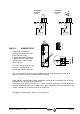
Compact Drive
Integrates specific functions of the Power Supply and modular Drives.
Specific of the Power Supply: With the Error Reset input (pin 3), it is possible to remove the
errors at the compact drive (see appendix D, resettable errors). When activated, (24V)
those errors are eliminated. If the cause of the error persists, the "status display" will show
the error again. But if it is a major error, it can only be eliminated by powering the unit off
and back on. Pins 1 and 2 offer a 24 Vdc output for the user. The maximum output
current is 100 mA.
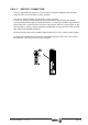
Specific of the modular Drive: control signals. The “Drive Enable” and “Speed Enable” inputs
(pins 4 and 5) together with the velocity command govern the motor. The consumption of
these control signals is between 4.5 and 7 mA. The following page describes the behavior
of the drive depending on these control signals.
The “Drive OK” contact (pins 6 and 7) will stay closed as long as the compact drive runs
properly.
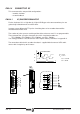
New: The “Prog Out” contact (pins 8 and 9) is a user programmable output by means of the
drive's internal parameter OP5 -F00291-. Its value may be forced with variable
OV5 -F00292-.
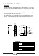
1 + 24 Vdc (out)
Internal
Power
Supply
output
Positive Voltage Output. (24 Vdc, 100 mA)
2 0 Vdc (out) "0 V" Reference.
3 Error Reset System Error Reset input. (24Vdc) (4.5-7mA)
4 Drive Enable
Control
Signals
Motor current enable. (24Vdc)
5 Speed Enable Drive Speed Enable. (24Vdc)
6Drive Ok
Module Status Contact (it opens in case of failure)
Limit: 1 Amp at 24 Vdc.
7Drive Ok
8 Prog Out
Programmable internal contact Limit: 1 Amp at 24 Vdc.
9 Prog Out
10 CHASSIS Chassis connection.