
Specifications


EM - 30 Electronic Modules Ver. 0002
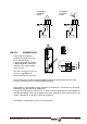
EM.4.3 CONNECTOR X2, CONTROL
Modular drive:
When the control circuit is supplied with 24 Vdc (pins 7 and 8) the drive runs an internal test. If
the system is OK, it closes the module status contacts (pins 4 and 5 "Drive OK). This contact
stays closed while the drive is supplied with 24 Vdc and it runs properly. To govern a motor,
the drives also needs energy at the Power Bus.
The maximum internal consumption of the 24 Vdc supply input is 2 Amp for the bigger
Drives. The internal circuits are protected by a 2.5Amp fuse.
See the characteristics table of the previous sections.
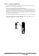
With the “Drive Enable” and “Speed Enable” inputs (pins 2 and 3) together with the velocity
command, it is possible to govern the motor. The consumption of these control signals is
between 4.5 and 7 mA. A later graph shows the behavior of the Drive depending on the “Drive
Enable” and “Speed Enable” inputs
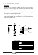
1GND
Control
signals
Reference "0V" for control signals.
2 Drive Enable Through-the-motor current enable (24Vdc)
3 Speed Enable Drive Speed Enable (24Vdc)
4Drive Ok
Module status contact (it opens in case of failure)
Limit: 1 Amp at 24 Vdc.
5Drive Ok
6 CHASSIS Chassis connection.
70 Vdc (in)
Supply input
for the control
circuit.
Reference "0V".
8 + 24 Vdc (in) Positive voltage input (21 Vdc ... 28 Vdc).