
Specifications


EM - 26 Electronic Modules Ver. 0002
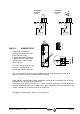
Before handling these terminals proceed as follows:
1st Disconnect the Mains voltage at the electrical cabinet.
2nd Wait before handling these terminals
The module needs time to bring the voltage at the power bus down to safe
values (< 60Vdc). The fact that the green “DC BUS ON” light is off does
not mean that it is safe to handle the power bus.
The discharge time depends on the number of elements connected to this
Bus and it is approximately 4 minutes..
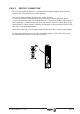
Terminals Ri, Re, L+ are used for configuring the Ballast circuit which dissipates the energy
generated when braking the motors.
By short-circuiting the terminals (Ri, L+), the system is configured so as to work with the
internal resistor of the compact drive module. Up to 45 °C (113 °F), this internal resistor
dissipates the power indicated in the previous characteristics table. It also incorporates a
protection against overtemperature which issues an error 301 when reaching
105 °C (221 °F).
By removing this jumper (Ri, L+) an external resistor may be connected between Re and L+
which will then dissipate the energy.
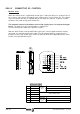
See the drawing on the next page.
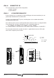
The following graphs show the power derating of the compact drives:
60
°C (°F)
Internal
Ballast
Power (W)
45 (113)
80
15 (59)
ACD/SCD 1.08
120
Internal
Ballast
Power (W)
45 (113)
160
15 (59)
ACD/SCD 1.15
200
Internal
Ballast
Power (W)
45 (113)
267
15 (59)
ACD/SCD 1.25
240
Internal
Ballast
Power (W)
45 (113)
320
15 (59)
ACD/SCD 2.50
ACD/SCD 2.75
°C (°F) °C (°F)
°C (°F)