
Specifications


Electronic Modules Ver. 0002 EM - 25
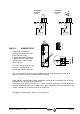
EM.3.3.1 POWER CONNECTORS
They are used for connecting the
compact drive to mains (L1, L2, L3) and
to the motor (U, V, W). They also have
the necessary terminals for connecting
an external Ballast resistor.
For the ACD1... and SCD1... type drives,
this same upper connector gives access
to the Power Bus (L+, L-).
The ground connection of the cable
shields is made from the vertical plate
next to these connectors.
The ACD2... and SCD2... provide the Bus
via the lower connector like modular
drives.
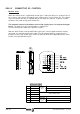
2 plates are provided with each module to
make this connection and another one for
connecting the chassis to each other.
The equipment must be protected with fuses on the three-phase supply
lines L1, L2 and L3.
Follow the instructions on the installation chapter (IN).
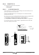
When connecting an external Ballast Resistor to the Compact Module,
check that the ohmage of the resistor is equal to than that of the internal
Ballast Resistor. See the characteristics table and the IN chapter of the
installation manual. Therefore, the RM-15 MUST NOT be used with the
Compact drives.
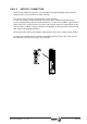
When connecting the drive module with its corresponding motor, connect
Terminal "U" of the drive module with the corresponding "U" phase of the
motor, same as terminals "V-V", "W-W" and "Ground-Ground".
Otherwise, it will not run properly. The cable hose must have a metallic
shield which must be connected to the drive's ground terminal and not to
that of the motor in order to comply with CE directives.
ACD1 ACD2 ACD2
SCD1 SCD2 SCD2
power ballast
Gap between terminals (mm) 8.1 12.1 10.16
Max. tightening torque (Nm) 1 2 1.6
Maximum Section (mm2) 4 16 10