
Specifications


EM - 24 Electronic Modules Ver. 0002
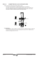
EM.3.3 CONNECTORS OF THE COMPACT DRIVE
The next diagram shows the elements appearing on the front plate of the Compact Drive:
1) Power connectors for motor and mains connection. Access to the power bus.
2) Fuses to protect the internal control circuit.
Two 1 Amp (T) / 500V slow fuses on the power supply lines.
3) Sercos Interface connectors.
4) Status Display. Shows the status information of the drive itself or the corresponding error
code.
5) Compact Drive Status Leds. Activation of the Ballast circuit, presence of power at the
Bus and 24 Vdc available.
X1) Connector for the internal 24 Vdc power supply (two-phase 380-460 Vac).
X2) Connector for the basic control signals.
X3) Connector with two possible uses:
- as output of the Encoder simulator.
- as input of the second feedback for the position loop.
X4) Connector for the motor speed feedback. Encoder or Resolver.
X5) Serial line connector
SL1) Slot for cards: A1, 16DI-8DO and 8DI-16DO.
SL2) Slot for cards: 16DI-8DO and 8DI-16DO.
DDS PROG MODULE) Accessory for adjusting and monitoring the system, it can be
mounted into the compact drive. Available upon request.