
Specifications


Electronic Modules Ver. 0002 EM - 21
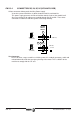
EM.2.3.1 POWER CONNECTORS
The upper connectors are for
connecting the motor.
The ground connection of the cable
shields is made from the vertical plate
next to the connectors.
The bottom connectors correspond to
the power bus input. The drive needs
456-800Vdc which can vary depending
on the Mains voltage and the load. The
power supply module is in charge
supplying this voltage.
2 plates are supplied with each module
for this connection and another one for
connecting the chassis with each
other.
When connecting the drive module and its corresponding motor, connect
terminal "U" of the drive module with the terminal corresponding to the
"U" phase of the motor as well as terminals "V-V", "W-W" and "Ground-
Ground".
Otherwise, it might not perform properly.
The cable must have a metal shield which must be connected to the
ground terminal of the drive and NOT to that of the motor in order to
comply with EEC directives.
Before handling these terminals, proceed as follows:
1st Disconnect the Mains voltage at the electrical cabinet.
2nd Wait, before handling these terminals
The power supply module takes about 4 minutes (depending on the
number of elements connected) to bring the power bus voltage down to
safe values (< 60Vdc). The green “DC BUS ON” light off does
NOT mean
that we can handle the power bus.
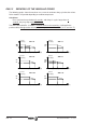
AXD/SPD AXD/SPD AXD/SPD AXD2 AXD3.100 AXD3.150
1.08/15 1.25 1.35 SPD2 SPD3.100 SPD3.150
Gap between terminals (mm) 7.5 7.5 8.1 10.1 15.1 18.8
Max. ti
g
htenin
g
torque (Nm) 0.6 0.6 1 1.7 7 7
Maximum Section (mm2) 2.5 4 4 10 25 50