
Specifications


EM - 20 Electronic Modules Ver. 0002
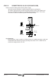
EM.2.3 CONNECTORS OF THE MODULAR DRIVE
The next figure shows the elements appearing on the front plate of the modular drive:
1) Power connectors for motor connection.
2) 2.5 Amp (F) / 250V Fast fuse.
To protect the internal control circuits.
3) Sercos Interface connectors.
4) Status Display. Shows status information for the drive itself or the relevant code when
there is an error.
5) Power connectors at the bottom to power the Drive module.
X1) Connector for module interconnection through the internal BUS.
A connector is supplied with each module for connecting it to the BUS. This connection is
described in detail in the section corresponding to the power supply.
If during system setup or maintenance, any module is constantly generating an error, the
whole system is completely disabled. To temporarily ignore this error, disconnect the
internal bus of that module and keep the other ones connected.
X2) Connector for the basic control signals.
X3) Connector with two possible uses:
- as output of the Encoder simulator.
- as input of a second feedback for the position loop.
X4) Motor speed feedback connector.
X5) Serial line connector.
SL1) Slot for cards: A1, 16DI-8DO and 8DI-16DO.
SL2) Slot for cards: 16DI-8DO and 8DI-16DO.