
Specifications


Electronic Modules Ver. 0002 EM - 15
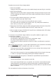
Procedure to turn on the Power Supply module:
1. At the PS-xxA models.
Supply 24 Vdc to the control circuits of the module through connector X2 (pins 9 and 10).
1. At the XPS and PS-25B.
Apply power to the Auxiliary Power Supply from Mains through connector X3 (pins 2 and
3). These will power the control circuits of the module and provide 24 Vdc at connectors
X4, X5 and X6.
2. The Power Supply module will check the system status.
If not OK, it will turn on the red "FAULT" lamp.
If the status is OK, the "System OK" contact will close (pins 6 and 7).
This contact will stay closed while the control circuits stay under power and while no
errors come up at any of the system modules.
3. Apply power to the Power Supply from Mains through the power connectors on top of the
module. The soft start will begin and the red "FAULT" lamp will turn off.
4. After 4 seconds, the green “DC BUS ON” lamp will turn on indicating that the DC voltage
is now available at the "Power Bus".
If an error occurs at the Power Supply module or at any Drive module it supplies to, the
system will act as follows:
The green “DC BUS ON” light will go off.
The red "FAULT" light will stay on if the error is at the power supply.
The "FAULT" light will blink if the error is at some drive.
It will eliminate the voltage supply to the Power Bus (it does not eliminate the capacitors'
charge).
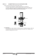
With the Error Reset input (pin 1), it is possible to eliminate the errors at the drives constituting
the system (See appendix B, resettable errors) and it acts as follows:
It will normally be at 0V. When activated (24V), the errors existing in the memory of each
one of the system modules will be deleted.
If the cause of the error persists, the corresponding module will show it again. If the error
is serious, it can only be eliminated by powering the unit down and back up.
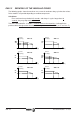
The System Speed Enable input (pin 5) is related to the "Speed Enable" input of the drive
modules.
"System Speed Enable", must normally be at 24 Vdc.
If the "System Speed Enable" pin is set to 0 Vdc, all servo drives connected to the power
supply through the same internal Bus will brake their motors at maximum torque and
once stopped or the limit time (programmable by parameter GP3) has elapsed, the motor
torque is removed.
The consumption of each input is between 4.5 and 7 mA.