
Specifications


EM - 14 Electronic Modules Ver. 0002
EM.1.3.2 X1 CONNECTOR, INTERNAL BUS
Interconnects all the elements of the Servo Drive System. All the modules powered with the
same Power Supply must be connected to this Bus and it is required to run it. The Bus must
not be disconnected while the system is running.
A ribbon cable is provided with each module (Power Supply or Drive) for this connection.
When using two Power Supply modules within the same Servo system,
each group must carry its own internal Bus.
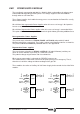
EM.1.3.3 X2 CONNECTOR, CONTROL
This connector is used to control the power supply module.
The internal circuits of the nonregenerative Power Supplies PS-xxA require an external 24 Vdc
supply. That's why their X2 connector has three more terminals. An 1.25 Amp fuse protects
the internal circuits.
System O. K.
7
6
5
8
4
1
9
10
+24 Vdc
0 Vdc
X2
1
10
(Phoenix,
5.08mm)
X2
PS-25A
PS-65A
3
2
System O. K.
7
6
5
4
1
System
Speed Enable
Error Reset
GND
X2
1
7
(Phoenix,
5.08mm)
X2
PS-25B
XPS-25
XPS-65
3
2
System
Speed Enable
Error Reset
GND
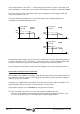
1 Error Reset System Error Reset Input (24 Vdc) (4.5 - 7 mA)
2 Not connected
3GND
0 Volts Reference for digital inputs
Error Reset (1) and System Speed Enable (5)
4 Not connected
5 System Speed Enable General System Speed Enable (24 Vdc (4.5 - 7 mA))
6System Ok
Contact indicating module estatus
(Opens when fault) Limit: 1 Amp at 24 Vdc
7System Ok
8 CHASSIS Chassis connection (only on PS-xxA models)
90 Vdc
Voltage for Control circuits (only on PS-xxA models)
between 21 and 28 Vdc (maximum consumption: 1 Amp)
10 +24 Vdc