
Specifications


Electronic Modules Ver. 0002 EM - 13
In the case of the PS-25B power supply, it will be enough to have all three phases of Mains
The start process begins when the "FAULT" lamp stops blinking and it is over, the "DC BUS
ON" lamp comes on.
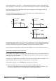
Before handling these leads, proceed in the following order:
1st Stop the motors.
2nd Disconnect the Mains voltage at the electrical cabinet.
3rd Wait, before handling these leads.
The Power Supply module needs time to decrease the voltage of
the Power Bus down to safe values (< 60Vdc). The green "DC BUS
ON" light off does NOT mean that it is safe to handle the Power
Bus. The discharge time is about 4 minutes depending on the
number of elements connected.
The Power Buses of different Power Supply Modules MUST NEVER be
connected in parallel.
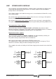
Inductive filter -Choke- connection terminals. (only at XPS)
The XPS-25 and XPS-65 power supplies offer the connection terminals labeled CH1 and CH2
at the bottom of the module for connecting the inductive filter. See attached table.
This inductance is a must to filter the current circulating from the Power Bus to Mains.
Fagor supplies the CHOKE XPS-25 and
CHOKE XPS-65 for this application.
Use cables with the maximum section
allowed (16 and 50 mm
2
) and shorter
than 2 meters (6 feet). They do not have
to be shielded.
The inductance is an absolute must for the operation of a regenerative
power supply.
Installing a Filter with an inductance other than the one recommended in
the general characteristics table may cause severe damage to the unit.
EKOHC
52-SPX
EKOHC
56-SPX
euqrotgninethgit.xaMmN2mN7
noitceselbacmumixaMmm61
2
mm05
2