
Specifications


EM - 12 Electronic Modules Ver. 0002
If this jumper between "Ri" and "L+" is eliminated and no external resistor is connected, error
215 or 304 will be issued. In the case of the PS-25B module, the Power bus will not be loaded.
The power supply carries a protection against over-temperatures which triggers error 301
when reaching 105°C (221°F).
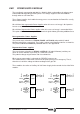
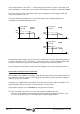
The power being dissipated by these resistors depends on the ambient temperature
according to the following derating curves.
Regenerative power supplies (XPS) also have a small Ballast Circuit for dissipating energy in
case of an emergency. This emergency is issued when there is no connection to Mains and
the Ballast circuit activating value is exceeded (see general characteristics table).
The performance of the Ballast resistor of the XPS-65 does not suffer at high temperatures.
Connection terminals for the Power Bus
At the bottom of the module, covered by screwed on lid, there are the connection terminals for
the Power Bus. This Bus supplies a DC voltage of about 600 Vdc (when the Mains voltage is
380 Vac) for the drive modules.
Two plates are supplied with each module to join the terminals of the adjacent modules. The
fastening torque at these terminals must be between 2.3 and 2.8 Nm.
Fagor Power Supplies have a Soft Start for charging this Power Bus.
The Soft start begins when two necessary and sufficient conditions are met:
· No errors at the modules connected to that Power Supply through the internal bus (X1).
· Presence of the three phases at the input of the Power Supply module.
°C (°F)
45 (113)35 (95)
600
520
PS-25A
Internal Ballast
Power (W)
XPS-25
600
900
15 (59)
°C (°F)
Internal Ballast
Power (W)
PS-65A
45 (113)
°C (°F)
45 (113)35 (95)
400
280
PS-25B
Internal Ballast
Power (W)