
Specifications


Electronic Modules Ver. 0002 EM - 11
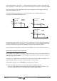
EM.1.3.1 POWER CONNECTORS OF THE POWER SUPPLIES
Terminal strip for connection to Mains.
The phases may be connected in any sequence.
The ground connection of the cable shields is made from
the vertical plate next to the terminal strip.
The equipment must be protected with fuses on the three-phase line L1, L2 and
L3 as instructed on the chapter IN.
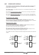
Terminal strip for the external Ballast Resistor.
The drive is supplied from factory with a wire jumper between terminals "Ri" and "L+". This
configures the Power Supply to work with its internal Ballast resistor.
If the internal resistor cannot handle
enough power, it could be set up to
work with an external resistor. The
following diagram shows the
configuration for an external resistor.
MPC-4x...(mm
2
)
Ready Made Cable
L3L2
From Mains
RTS
N
RST phases may
be connected in
any sequence.
L1
C
ONTROL
L-
L+
R. int
Configuration
for internal
resistor
Configuration
for external
resistor
R. ext
RM-15
PS
XPS
L+ReRi
L-
L+
R. int
PS
XPS
L+ReRi
C
ONTROL
ER
PS-25A PS-25B
XPS-25 PS-65A
XPS-65
Gap between terminals (mm) 8.1 10.16
Max. tightening torque (Nm) 1 1.5/1.7
Maximum Section (mm2) 4 10
PS-25A PS-25B XPS-25 PS-65A
XPS -65
Gap between terminals (mm)
8.1 10,16 12.1 18.8
Max. tightening torque (Nm)
11,52 7
Maximum Section (mm2)
4101650