
Specifications


Electronic Modules Ver. 0002 EM - 9
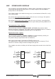
EM.1.3 POWER SUPPLY CONNECTORS
1. Power connectors for Mains.
2. Power connectors for the external Ballast resistor.
3. Ground connector for the cable hose from Mains and intermodular Chassis connections.
4. Lamps indicating the status of the Main Power Supply.
“FAULT”. When blinking, it indicates that one or several Mains phases are missing.
“FAULT” on, it indicates an error specified at the display of the drives.
"BALLAST" it comes on when the energy dissipating Ballast circuit is activated.
“DC BUS ON” comes on when the module offers all its power at the Bus.
And at the XPS:
“REGEN” comes on when the module is working in Energy Regenerating mode.
5. Power Bus supplying power to the Drive modules through metal bars.
6. Connectors for the inductance needed on XPS models.
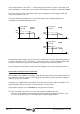
7. Lamps indicating the status of the Auxiliary Power Supply and reset button.
"RESET" initializes the Auxiliary 24 Vdc Power Supply after an overvoltage error.
“OVER VOLTAGE” indicates an overvoltage error at the 24 Vdc output.
“OVER CURRENT” indicates and overcurrent error at the 24 Vdc output.
“ON”, it comes on when the 24 Vdc is available.
X1 Connector intermodular communications. Internal Bus.
X2 Connector providing access to the basic control signals.
X3 Input connector supplying to the internal Auxiliary Power Supply from Mains.
X4, X5 and X6 Output connectors of the Auxiliary Power Supply offering 24 Vdc.
mm
K
g
·m
2
Nm
°C
Kw
÷ 25.4
÷ 0.113
x 1.8
inch
lb·in·sec
2
lb·in
°F
HP
÷ 0.113
÷ 0.746
+ 32
Metric Imperial
Conversion table
to