
Specifications


AM - 22 Asynchronous Motors Ver. 0002
12
3
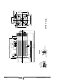
AM.8 CONNECTORS
1
Terminal box for power and brake (option)
connection.
2
Encoder feedback connector
3
Terminal box or connector for the fan (the
1
,
2
,
3
, name is not printed on the motor)
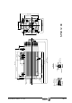
AM.8.1 POWER AND BRAKE CONNECTION
It is done through an internal terminal box.
* Power terminals.
* Internal thermal switch contacts (Klixon 150°C (302°F)).
* Brake contacts as an option.
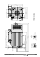
There is internal thermal switch as a protection against overtemperature. It is a normally
closed contact that opens when the temperature exceeds 150°C (302°F). It has no polarity
and withstands up to 250V/2.5A. This contact should be included in the Emergency chain.
Make sure that the U, V, W and Ground terminals of the Drive Module are connected
to the U1, V1, W1 and Ground terminals of the Motor respectively. Otherwise, the motor
would not work properly.
For further information about the characteristics of the power supply cables for the
asynchronous motors as well as the selection criteria, see chapter IN.
To control the brake a single-phase mains (220 Vac) connection is needed.
The brake must be released when applying these 220 Vac. That way, in case of a power
outage, the motor will be braked.
The windings of the motor have a star connection (as shown here) and it
cannot be changed for any reason because it would make it run
improperly.
Star
Connection
U1
V1
W1
Power Connector, in
1