
Specifications


E - 6 Protections Ver: 0002
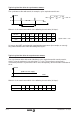
Typical cycle of the drive for synchronous motors.
The synchronous drive withstands, for example, cycles equivalent to this one:
Where In is the rated current which is the following for each drive (in Amps):
As long as the IGBTs are below their rated working temperature (for example, on start-up)
they will be allowed some more demanding initial cycles.
Typical cycle of the drive for asynchronous motors.
The asynchronous drive withstands indefinitely cycles equivalent to their rated current In,
which is also the maximum it can offer (that is: I
peak
=In). The maximum current limit is
sufficient to protect the asynchronous drives and, consequently, do not need the calculation of
the I
2
t.
Where In is the rated current which is the following for each drive (in Amps):
Time
Current
Ipeak = In = I
IGBT
/ sqr(2)
Time
Current
2·In
In
10 sec0.5 sec
Ipeak I 2 In
IGBT
==⋅
()
Irms = 2 In
2
0.5
10
+ In
2
9.5
10
=1.07 In
⋅⋅ ⋅ ⋅
AXD, ACD 1.08 1.15 1.25 1.35 2.50 2.75 3.100 3.150
Ipeak = In 5.6 10.6 19.6 28.5 35.4 53 80 106
AXD, ACD 1.08 1.15 1.25 1.35 2.50 2.75 3.100 3.150
In 4 7.5 12.5 17.5 25 37.5 50 75
Ipeak 8 15 25 35 50 75 100 150