
Specifications


B - 4 Errors Ver. 0002
EFFECT OF THE SYSTEM ERRORS
Activating any of the errors listed in this appendix causes certain effects on the system that
depend on the type of interface being used.
Analog interface.
The activated error is shown on the drive's display.
Sercos interface.
The activated error is shown on the drive's display.
This error is also displayed on the CNC screen.
The CNC may display the errors listed in this appendix as well as those
of the Sercos communication itself.
CNC actions
Activates bit 13 of DV31 -S135-
Activates the bit corresponding to that error in the DV1 -S11- variable.
Interrupts the execution of the program.
Stops the axes and the spindles.
Sets marks /ALARM and O1 to zero. These marks are always present in the PLC
program which will handle that emergency without having to know which error has
been activated.
Error reset.
The system will not start running until all the errors detected at the drive have been
eliminated. To eliminate these errors, their cause has to have disappeared and, then, an
"Error Reset" must be carried out.
This Reset may be carried out via X2(1) of the power supply module, or pin X2(3) of the
Compact Drive.
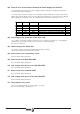
Certain errors cannot be reset or eliminated with this method. Those errors can only be
eliminated by turning the unit off and back on, but provided that the cause for the error has
been solved. These errors are:
1256505152 53 54
55 100 101 102 103 104 105 109 211
502 503 504 700 701 702 703 704 705
706 707 801 802 803 804 805 806 900
Stopping the motor.
Activating certain errors cancels the current through the motor. These errors are:
2456505152 53 54
55 66 67 68 69 109 200 202 203
211 212 213 214 215 301 302 303 304
306 501 502 503 504 602 603 604 605
606 607 608 700 701 702 703 704 705
706 707 801 802 803 804 806