
Specifications


Parameters, Variables and Commands Ver. 0002 A - 23
9. GROUP OF INPUTS “I”
IP1.# O (F900.#) AnalogReferenceSelect
Function: Selects the analog input used as velocity command.
Valid values: 1: Analog input 1 (by default)
2: Analog input 2
IP5 O (F909) DigitalInputVoltage
Function: Its four least significant bits configure the digital inputs of the 8I-16O and 16I-8O
cards to operate at an input voltage of 5 Vdc or 24 Vdc.
The card for connectors X6 and X7 cannot be configured by this parameter.
Bits 0 (LSB) and 1 configure the inputs of slot SL1.
Bit 0 configures the group of inputs I1-I8.
Bit 1 configures the group I9-I16.
Bits 2 and 3 configure the inputs of slot SL2.
Bit 2 configures the group I17-I24.
Bit 3 configures I25-I32.
Valid values: 0: inputs configured for 24 Vdc (by default at all four bits)
1: inputs configured for 5 Vdc
Version: Operative from version 04.01 on
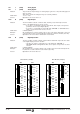
IP10 O (F901) I1IDN
IP11 O (F902) I2IDN
IP12 O (F903) I3IDN
IP13 O (F904) I4IDN
Function: Contain the identifiers of the parameters or variables which will be assigned the logic
value of the electrical signal going into the Drive through:
pin-1 (referred to pin-5) for IP10
pin-2 (referred to pin-5) for IP11
pin-3 (referred to pin-5) for IP12
pin-4 (referred to pin-5) for IP13
Default value: 0 (not assigned)
Examples: IP10 = GV24 (pin 1 referred to 5, is the Strobe for Set selection)
IP11 = BV1 (pin 2 referred to 5, performs the Halt-hardware function)
IP12 = 0 (pin 3 referred to 5, performs no function)
Version: The parameters IP12 and IP13 are available from version 02.01 on.
IP1=2
IP1=1
IP10 -F00901-
Analog
X6(1)
X6(2)
X6(3)
X6(4)
IP13 -F00904-
Digital
HV5 - A1 Board IdPhysical Inputs
X7(5)
X7(4)
X7(3)
X7(2)
IV1 -F00905-
IV2 -F00906-
IV10 -F00907-
V (+)
V (-)
V (+)
V (-)
IP11 -F00902-
IP12 -F00903-
IP1 -F00900-