
Specifications


DS - 16 Design Ver. 0002
DS.4 CM-60 SELECTION GUIDE
The CM-60 is a module that increases the electrical capacitance of the power bus in 4
millifarads. It should be installed on machines with very short duty cycles (very repetitive
accelerations and decelerations) and with low braking energy. Punch presses are a typical
example of this.
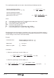
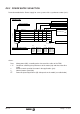
The following table indicates how much energy can be stored in Watts second, when the Bus
voltage increases from the nominal value
(Vbus)
to the Ballast circuit activating value
(Vballast
ON
).
Considering the different combinations of power supplies + CM-60 modules and different
mains voltages.
where:
C
comes in farads
V
in volts DC
W
in watts second (jules)
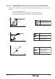
DS.5 BALLAST RESISTOR SELECTION GUIDE
Calculate the value of:
Wm
is the energy generated by the braking of each system motor.
Pe
is the rms power generated by all braking of all the motors throughout a complete
duty cycle.
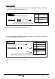
Based on the following formulae:
where:
Jt
is the total inertia of the servo drive system (motor
+ mechanics) (Kg.m
2
)
n
is the turning speed of the motor when the braking
starts (rpm)
Wmi
is the energy of each braking.
during a cycle of time
T
(Ws)
Wp
is the potential energy lost by the mass of the
machine for as long as the braking lasts. Only on
axes not compensated (Ws)
ti
is the braking time where the
Wmi
energy is
generated (sec)
T
is the time of full cycle (sec)
∆
h
is the height lost when braking (m)
Wmx
will be the maximum of all the
Wm
Wm Wp Jt
n
Ws
Wp m g h
Pe
W
t
T
W
mi
i
i
=+⋅⋅
⋅
=⋅⋅
=
∑
1
2
2
60
2
2
π
()
()
∆
W C Vballast Vbus Ws
ON
=⋅⋅ −
1
2
22
()()
V mains: 380 Vac 460 Vac
PS-25x 76 59
PS-65A 81 63
XPS-25 52 96
XPS-65 93 172
CM-60 + PS-25x 507 394
CM-60 + PS-65A 511 397
CM-60 + XPS-25 227 421
CM-60 + XPS-65 269 498
Watts·sec