
Specifications


Synchronous Motors Ver. 0002 SM - 15
SM.6 INSTALLATION AND MOUNTING CONDITIONS
Before installing it onto the machine, the anti-rust paint should be removed from the rotor shaft
and the flange.
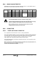
The motor admits the B5, V1 and
V3 mounting methods.
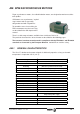
The ambient conditions
recommended for the motor are the
ones indicated in the general
characteristics bearing in mind that:
It must always be in a dry and clean place.
Mounted so it is easily inspected, cleaned and maintained.
Free of corrosive atmosphere and / or explosive gasses or liquids.
If the motor is going to be continuously exposed to oil splashes, it should be protected
with a guard.
SM.7 RADIAL AND AXIAL LOADS
The misalignment between the motor and the machine causes vibrations on the shaft and
decreases the life span of the roller bearings and couplings.
Please follow these advises in order to avoid those problems:
Use flexible couplings for direct coupling.
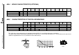
Avoid radial and axial loads on the motor shaft which exceed the values in the table
below:
Note: For radial and axial loads combined, decrease the value of the permitted radial force Fr
to 70% of the table value.
When installing pulleys or gears for transmission, avoid hitting the shaft.
Use some tool that is supported in the
threaded hole on the shaft to insert the pulley
or the gear.
B5 V1 V3
Fa
Fr
A
Motor Type Axial Force Fa Radial Force Fr Distance A
FXM1 105 Nw (23.6 lbf) 500 Nw (112.4 lbf) 15 mm (0.59")
FXM3 138 Nw (31 lbf) 660 Nw (148.3 lbf) 20 mm (0.78")
FXM5 157 Nw (35.3 lbf) 745 Nw (167.4 lbf) 25 mm (0.98")
FXM7 336 Nw (75.5 lbf) 1590 Nw (357.4 lbf) 29 mm (1.14")