
Specifications


Applications Ver. 0002 AP - 35
Note:
the numerical data of these parameters and variables are given in the units used by the DOS-based
"ddssetup.exe". The Winddssetup (for Windows) may use different units which will be displayed on the screen.
AP.7 HALT FUNCTION
Activating the HALT function means setting the velocity command to zero while keeping the
rotor locked (with torque). As opposed to the effect of deactivating the Speed_Enable function,
the Halt function does not free the motor when it has stopped it.
It can be activated through an electrical signal at one of the digital inputs of the drive, by the
monitoring program through the serial line or through the Sercos interface.
The Halt function is activated (stops the motor) when:
when applying zero volts at the electrical input assigned to variable BV1 -F00201-, or
when requested from the monitoring program (variable BV3 -F00202-= 0), or
when requested from the PLC of the CNC via Sercos (bit 13 of DV32 -S00134- is set to
"0").
By programming drive variable BV1, one of the four digital inputs of connector X6 can perform
the Halt function. To make the motor stop more smoothly, its deceleration can be limited with
parameter SP65 (SP70=1, SP100=1).
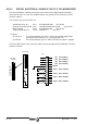
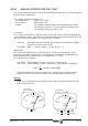
This is a programming example with a graph showing its operation:
IP10 -F00901- = BV1 -F00201-
SP70 -F01610- = 1
SP100 -F01611- = 1
SP65 -F01609- = 500 rad/sec
2
This way, when pin 1 (referred to pin 5) of connector X6 receives zero volts, BV1 -F00201- will
assume the zero value and the Halt function will be activated. The motor will stop with a
maximum deceleration of 500 rd/s
2
and will stay locked. With 24 V at that pin, the servo drive
will continue to follow the velocity command.
OR
Halt Function
BV1 -F201-
BV3 -F202-
DV32 -S134-
(bit 13)
HaltDrivePin
HaltDriveDnc
Halt (Sercos)
time
AnalogInput1
Digital
Input
24 V
0 V
time
time
IV1 -F905-
SV8 -F1613-
time
Velocity
Command
Final
SV7 -F1612-
VelocityCommand
BeforeFilters
SP65 -F1609-
with SP70 -F1610- = 1
& SP100 -F1611- = 1
V
1-5 X6